Nissan Sentra Service Manual: 2135 TP Sensor
DTC Logic
DTC DETECTION LOGIC
NOTE:
If DTC P2135 is displayed with DTC P0643, first perform the trouble diagnosis for DTC P0643. Refer to EC-353, "DTC Logic".
| DTC No. | CONSULT screen terms (Trouble diagnosis content) | DTC detecting condition | Possible cause |
| P2135 | TP SENSOR-B1 (Throttle/Pedal position sensor/switch ą▓ąéčÜAą▓ąéč£ / ą▓ąéčÜBą▓ąéč£ voltage correlation) | Rationally incorrect voltage is sent to ECM compared with the signals from TP sensor 1 and TP sensor 2. |
|
DTC CONFIRMATION PROCEDURE
1.PRECONDITIONING
If DTC Confirmation Procedure has been previously conducted, always perform the following procedure before conducting the next test.
- Turn ignition switch OFF and wait at least 10 seconds.
- Turn ignition switch ON.
- Turn ignition switch OFF and wait at least 10 seconds.
TESTING CONDITION:
Before performing the following procedure, confirm that battery voltage is more than 8 V at idle.
>> GO TO 2.
2.PERFORM DTC CONFIRMATION PROCEDURE
- Start engine and let it idle for 1 second.
- Check DTC.
Is DTC detected? YES >> Proceed to EC-438, "Diagnosis Procedure".
NO >> INSPECTION END
Diagnosis Procedure
1.CHECK THROTTLE POSITION SENSOR POWER SUPPLY
- Turn ignition switch OFF.
- Disconnect electric throttle control actuator harness connector.
- Turn ignition switch ON.
- Check the voltage between electric throttle control actuator harness connector and ground.
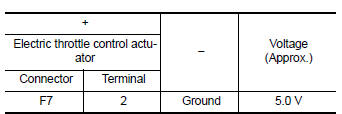
Is the inspection result normal? YES >> GO TO 3.
NO >> GO TO 2.
2.CHECK THROTTLE POSITION SENSOR POWER SUPPLY CIRCUIT
- Turn ignition switch OFF.
- Disconnect ECM harness connector
- Check the continuity between electric throttle control actuator harness connector and ground.
- Also check harness for short to ground.
Is the inspection result normal? YES >> Perform the trouble diagnosis for power supply circuit.
NO >> Repair or replace error-detected parts.
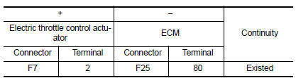
3.CHECK THROTTLE POSITION SENSOR GROUND CIRCUIT
- Turn ignition switch OFF.
- Disconnect ECM harness connector.
- Check the continuity between electric throttle control actuator harness connector and ECM harness connector.
- Also check harness for short to power.
Is the inspection result normal? YES >> GO TO 4.
NO >> Repair or replace error-detected parts.
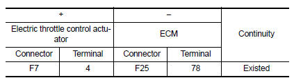
4.CHECK THROTTLE POSITION SENSOR INPUT SIGNAL CIRCUIT
- Check the continuity between electric throttle control actuator harness connector and ECM harness connector.
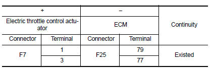
- Also check harness for short to ground and to power.
Is the inspection result normal? YES >> GO TO 5.
NO >> Repair open circuit or short to ground or short to power in harness or connectors.
5.CHECK THROTTLE POSITION SENSOR
Check throttle position sensor. Refer to EC-439, "Component Inspection (TP Sensor)".
Is the inspection result normal? YES >> Check intermittent incident. Refer to GI-39, "Intermittent Incident".
NO >> Replace electric throttle control actuator. Refer to EM-27, "Removal and Installation".
Component Inspection (TP Sensor)
1.CHECK THROTTLE POSITION SENSOR
- Turn ignition switch OFF.
- Reconnect all harness connectors disconnected.
- Perform ą▓ąéčÜ Throttle Valve Closed Position Learningą▓ąéč£. Refer to EC-139, "Work Procedure".
- Turn ignition switch ON.
- Set selector lever to D (CVT) or 1st (M/T) position.
- Check the voltage between ECM harness connector terminals as per the following conditions.
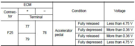
Is the inspection result normal? YES >> INSPECTION END
NO >> Replace electric throttle control actuator. Refer to EM-27, "Removal and Installation".
 P2127, P2128 APP Sensor
DTC Logic
DTC DETECTION LOGIC
DTC No.
CONSULT screen terms
(Trouble diagnosis content)
DTC detecting condition
Possible cause
P2127
APP SEN 2/CIRC
(Throttle/Pedal p ...
 P2138 APP Sensor
DTC Logic
DTC DETECTION LOGIC
NOTE:
If DTC P2138 is displayed with DTC P0643, first perform the trouble
diagnosis for DTC P0643. Refer to
EC-353, "DTC Logic".
DTC No.
CONSUL ...
Other materials:
Fuel-filler cap
WARNING
Gasoline is extremely flammable and
highly explosive under certain conditions.
You could be burned or seriously
injured if it is misused or mishandled.
Always stop the engine and do not
smoke or allow open flames or sparks
near the vehicle when refuelin ...
System
Tire pressure monitoring system
TIRE PRESSURE MONITORING SYSTEM : System Diagram
TIRE PRESSURE MONITORING SYSTEM : System Description
The BCM has pressure judgment and trouble diagnosis functions. When the
BCM detects low inflation pressure
or another unusual symptom, the low tire pr ...
Text messaging
WARNING
Laws in some jurisdictions may restrict
the use of some of the applications and
features, such as social networking and
texting.
Laws in some jurisdictions may restrict
the use of ŌĆ£Text-to-SpeechŌĆØ. Check local
regulations before using this
feature.
...
