
Nissan Sentra Service Manual: P2138 APP Sensor
DTC Logic
DTC DETECTION LOGIC
NOTE:
If DTC P2138 is displayed with DTC P0643, first perform the trouble diagnosis for DTC P0643. Refer to EC-353, "DTC Logic".
| DTC No. | CONSULT screen terms (Trouble diagnosis content) | DTC detecting condition | Possible cause |
| P2138 | APP SENSOR (Throttle/Pedal position sensor/switch “D” / “E” voltage correlation) | Rationally incorrect voltage is sent to ECM compared with the signals from APP sensor 1 and APP sensor 2. |
|
DTC CONFIRMATION PROCEDURE
1.PRECONDITIONING
If DTC Confirmation Procedure has been previously conducted, always perform the following procedure before conducting the next test.
- Turn ignition switch OFF and wait at least 10 seconds.
- Turn ignition switch ON.
- Turn ignition switch OFF and wait at least 10 seconds.
TESTING CONDITION:
Before performing the following procedure, confirm that battery voltage is more than 8 V at idle.
>> GO TO 2.
2.PERFORM DTC CONFIRMATION PROCEDURE
- Start engine and let it idle for 1 second.
- Check DTC.
Is DTC detected? YES >> Proceed to EC-441, "Diagnosis Procedure".
NO >> INSPECTION END
Diagnosis Procedure
1.CHECK APP SENSOR 1 POWER SUPPLY
- Turn ignition switch OFF.
- Disconnect accelerator pedal position (APP) sensor harness connector.
- Turn ignition switch ON.
- Check the voltage between APP sensor harness connector and ground.
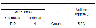
Is the inspection result normal? YES >> GO TO 3.
NO >> GO TO 2.
2.CHECK APP SENSOR 1 POWER SUPPLY CIRCUIT
- Turn ignition switch OFF.
- Disconnect ECM harness connector.
- Check the continuity between APP sensor harness connector and ECM harness connector.
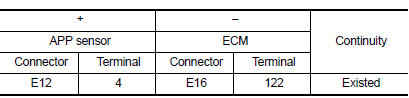
- Also check harness for short to ground.
Is the inspection result normal? YES >> Perform the trouble diagnosis for power supply circuit.
NO >> Repair or replace error-detected parts.
3.CHECK APP SENSOR 2 POWER SUPPLY
Check the voltage between APP sensor harness connector and ground.
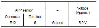
Is the inspection result normal? YES >> GO TO 5.
NO >> GO TO 4.
4.CHECK SENSOR POWER SUPPLY 2 CIRCUIT
Check sensor power supply 2 circuit. Refer to EC-444, "Diagnosis Procedure".
Is inspection result normal? YES >> Perform the trouble diagnosis for power supply circuit.
NO >> Repair or replace error-detected parts.
5.CHECK APP SENSOR GROUND CIRCUIT
- Turn ignition switch OFF
- Disconnect ECM harness connector.
- Check the continuity between APP sensor harness connector and ECM harness connector.
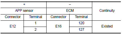
- Also check harness for short to power.
Is the inspection result normal? YES >> GO TO 6.
NO >> Repair or replace error-detected parts.
6.CHECK APP SENSOR INPUT SIGNAL CIRCUIT
- Check the continuity between APP sensor harness connector and ECM harness connector.
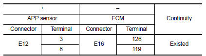
- Also check harness for short to ground and to power.
Is the inspection result normal? YES >> GO TO 7.
NO >> Repair or replace error-detected parts
7.CHECK APP SENSOR
Check APP sensor. Refer to EC-443, "Component Inspection (APP Sensor)".
Is the inspection result normal? YES >> Check intermittent incident. Refer to GI-39, "Intermittent Incident".
NO >> Replace accelerator pedal assembly. Refer to ACC-3, "Removal and Installation".
Component Inspection (APP Sensor)
1.CHECK ACCELERATOR PEDAL POSITION SENSOR
- Turn ignition switch OFF
- Reconnect all harness connectors disconnected.
- Turn ignition switch ON
- Check the voltage between ECM harness connector terminals as per the following condition.
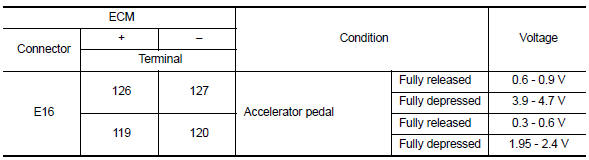
Is the inspection result normal? YES >> INSPECTION END
NO >> Replace accelerator pedal assembly. Refer to ACC-3, "Removal and Installation".
 2135 TP Sensor
DTC Logic
DTC DETECTION LOGIC
NOTE:
If DTC P2135 is displayed with DTC P0643, first perform the trouble
diagnosis for DTC P0643. Refer to
EC-353, "DTC Logic".
DTC No.
CONSUL ...
 Sensor power supply 2 circuit
Description
ECM supplies a voltage of 5.0 V to some of the sensors systematically divided
into 2 groups, respectively.
Accordingly, when a short circuit develops in a sensor power source, a
ma ...
Other materials:
P0711 Transmission fluid temperature sensor A
DTC Logic
DTC DETECTION LOGIC
DTC
CONSULT screen terms
(Trouble diagnosis content)
DTC detection condition
Possible causes
P0711
FLUID TEMP SENSOR A
(Transmission Fluid Temperature
Sensor A Circuit Range/
Performance)
When any of 1 or 2 is satisfied:
...
Timing chain
Exploded View
Timing chain slack guide
Timing chain tensioner
Timing chain
Oil pump drive chain
Crankshaft sprocket
Crankshaft key
Oil pump sprocket
Front cover
O-ring
O-ring
Valve timing control solenoid valve cover
O-ring
Valve timing control solenoid valve
(EXH)
...
Rear combination lamp
Exploded view
Rear combination lamp
Rear turn signal lamp bulb
Rear turn signal lamp socket
LED lamp harness connector
Rear combination lamp harness
connector
Back-up lamp bulb socket
Back-up lamp bulb
Removal and installation
Removal
Partially remove trunk side finis ...
