Nissan Sentra Service Manual: P2127, P2128 APP Sensor
DTC Logic
DTC DETECTION LOGIC
| DTC No. | CONSULT screen terms (Trouble diagnosis content) | DTC detecting condition | Possible cause |
| P2127 | APP SEN 2/CIRC (Throttle/Pedal position sensor/switch “E” circuit low) | An excessively low voltage from the APP sensor 2 is sent to ECM. |
|
| P2128 | APP SEN 2/CIRC (Throttle/Pedal position sensor/switch “E” circuit high) | An excessively high voltage from the APP sensor 2 is sent to ECM. |
DTC CONFIRMATION PROCEDURE
1.PRECONDITIONING
If DTC Confirmation Procedure has been previously conducted, always perform the following procedure before conducting the next test.
- Turn ignition switch OFF and wait at least 10 seconds.
- Turn ignition switch ON.
- Turn ignition switch OFF and wait at least 10 seconds.
TESTING CONDITION:
Before performing the following procedure, confirm that battery voltage is more than 8 V at idle.
>> GO TO 2.
2.PERFORM DTC CONFIRMATION PROCEDURE
- Start engine and let it idle for 1 second.
- Check DTC.
Is DTC detected? YES >> Proceed to EC-435, "Diagnosis Procedure".
NO >> INSPECTION END
Diagnosis Procedure
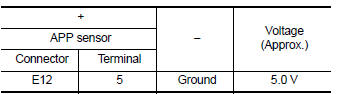
1.CHECK APP SENSOR 2 POWER SUPPLY
- Turn ignition switch OFF.
- Disconnect accelerator pedal position (APP) sensor harness connector.
- Turn ignition switch ON.
- Check the voltage between APP sensor harness connector and ground.
Is the inspection result normal? YES >> GO TO 3.
NO >> GO TO 2.
2.CHECK SENSOR POWER SUPPLY 2 CIRCUIT
Check sensor power supply 2 circuit. Refer to EC-444, "Diagnosis Procedure".
Is the inspection result normal? YES >> Perform the trouble diagnosis for power supply circuit.
NO >> Repair or replace error-detected parts.
3.CHECK APP SENSOR 2 GROUND CIRCUIT
- Turn ignition switch OFF.
- Disconnect ECM harness connector.
- Check the continuity between APP sensor harness connector and ECM harness connector.
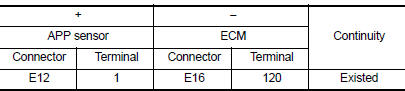
- Also check harness for short to power.
Is the inspection result normal? YES >> GO TO 4.
NO >> Repair or replace error-detected parts.
4.CHECK APP SENSOR 2 INPUT SIGNAL CIRCUIT
- Check the continuity between APP sensor harness connector and ECM harness connector.
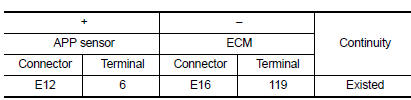
- Also check harness for short to ground and to power.
Is the inspection result normal? YES >> GO TO 5.
NO >> Repair or replace error-detected parts.
5.CHECK APP SENSOR
Check APP sensor. Refer to EC-436, "Component Inspection (APP Sensor)".
Is the inspection result normal? YES >> Check intermittent incident. Refer to GI-39, "Intermittent Incident".
NO >> Replace accelerator pedal assembly. Refer to ACC-3, "Removal and Installation".
Component Inspection (APP Sensor)
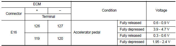
1.CHECK ACCELERATOR PEDAL POSITION SENSOR
- Turn ignition switch OFF.
- Reconnect all harness connectors disconnected.
- Turn ignition switch ON.
- Check the voltage between ECM harness connector terminals as per the following condition.
Is the inspection result normal?
YES >> INSPECTION END
NO >> Replace accelerator pedal assembly. Refer to ACC-3, "Removal and Installation".
 P2122, P2123 APP Sensor
DTC Logic
DTC DETECTION LOGIC
NOTE:
If DTC P2122 or P2123 is displayed with DTC P0643, first perform the
trouble diagnosis for DTC P0643.
Refer to EC-353, "DTC Logic".
DTC No ...
 2135 TP Sensor
DTC Logic
DTC DETECTION LOGIC
NOTE:
If DTC P2135 is displayed with DTC P0643, first perform the trouble
diagnosis for DTC P0643. Refer to
EC-353, "DTC Logic".
DTC No.
CONSUL ...
Other materials:
Wiring diagram
Interior room lamp control system
Wiring diagram
Illumination
Wiring diagram
...
Steering wheel
Exploded View
Driver air bag module
Steering wheel
Steering column assembly
Removal and Installation
REMOVAL
NOTE:
When reconnecting spiral cable, fix cable with a tape so that
fixing case and rotating part keep aligned. This
will omit neutral position alignment procedu ...
Precaution for work
When removing or disassembling each component, be careful not to damage
or deform it. If a component
may be subject to interference, be sure to protect it with a shop cloth.
When removing (disengaging) components with a screwdriver or similar
tool, be sure to wrap the component
with a ...
