Nissan Sentra Service Manual: Sensor power supply 2 circuit
Description
ECM supplies a voltage of 5.0 V to some of the sensors systematically divided into 2 groups, respectively.
Accordingly, when a short circuit develops in a sensor power source, a malfunction may occur simultaneously in the sensors belonging to the same group as the shorted-circuit sensor.
Sensor power supply 1
- Battery current sensor
- Crankshaft position (CKP) sensor (POS)
- Throttle position (TP) sensor
- Accelerator pedal position (APP) sensor 1
NOTE:
If sensor power supply 1 circuit is malfunctioning, DTC P0643 is displayed.
Sensor power supply 2
- Camshaft position (CMP) sensor (PHASE)
- Mass air flow (MAF) sensor
- Engine oil pressure (EOP) sensor
- Exhaust valve timing (EVT) control position sensor
- Accelerator pedal position (APP) sensor 2
- Intake manifold runner control valve position sensor
Diagnosis Procedure
1.CHECK ACCELERATOR PEDAL POSITION SENSOR 2 POWER SUPPLY CIRCUIT-1
- Turn ignition switch OFF.
- Disconnect accelerator pedal position (APP) sensor harness connector.
- Turn ignition switch ON.
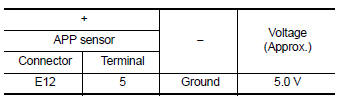
- Check the voltage between APP sensor harness connector and ground.
Is the inspection result normal? YES >> GO TO 4.
NO >> GO TO 2.
2.CHECK ACCELERATOR PEDAL POSITION SENSOR 2 POWER SUPPLY CIRCUIT-2
- Turn ignition switch OFF.
- Disconnect ECM harness connector.
- Turn ignition switch ON.
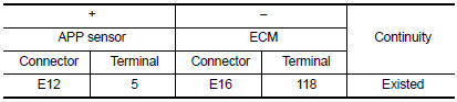
- Check the continuity between APP sensor harness connector and ECM.
CVT models
Is the inspection result normal? YES >> GO TO 3.
NO >> Repair or replace error-detected parts.
3.CHECK SENSOR POWER SUPPLY CIRCUITS
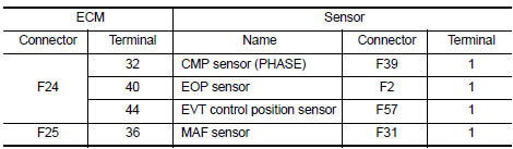
Check harness for short to power and short to ground, between the following terminals.
Is the inspection result normal? YES >> GO TO 4.
NO >> Repair or replace error-detected parts.
4.CHECK COMPONENTS
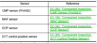
Check the following.
Is the inspection result normal? YES >> GO TO 5.
NO >> Repair or replace malfunctioning component.
5.CHECK APP SENSOR
Check APP sensor. Refer to EC-436, "Component Inspection (APP Sensor)".
Is the inspection result normal? YES >> Check intermittent incident. Refer to GI-39, "Intermittent Incident".
NO >> Replace accelerator pedal assembly. Refer to ACC-3, "Removal and Installation".
 P2138 APP Sensor
DTC Logic
DTC DETECTION LOGIC
NOTE:
If DTC P2138 is displayed with DTC P0643, first perform the trouble
diagnosis for DTC P0643. Refer to
EC-353, "DTC Logic".
DTC No.
CONSUL ...
 Brake pedal position switch
Component Function Check
1.CHECK BRAKE PEDAL POSITION SWITCH FUNCTION
With CONSULT
Turn ignition switch ON.
Select “ENGINE” using CONSULT.
Select “BRAKE SW1” in “DA ...
Other materials:
Dtc/circuit diagnosis
U1000 can comm circuit
Description
Refer to LAN-7, "CAN COMMUNICATION SYSTEM : System Description".
Dtc logic
DTC DETECTION LOGIC
CONSULT Display
DTC Detection Condition
Possible Cause
CAN COMM CIRCUIT
[U1000]
When IPDM E/R cannot communicate with CAN com ...
P0172 Fuel injection system function
DTC Logic
DTC DETECTION LOGIC
With the Air/Fuel Mixture Ratio Self-Learning Control, the actual mixture
ratio can be brought closely to the
theoretical mixture ratio based on the mixture ratio feedback signal from the
A/F sensors 1. The ECM calculates
the necessary compensation to correct th ...
Parts Requiring Angle Tightening
Use the Tool for the final tightening of the following engine parts:
Tool number : KV10112100 (BT-8653-A)
Camshaft sprocket (INT) bolt
Cylinder head bolts
Main bearing cap bolts
Connecting rod cap bolts
Crankshaft pulley bolt (No the angle wrench is required as bolt flange
is pr ...
