Nissan Sentra Service Manual: Brake pedal position switch
Component Function Check
1.CHECK BRAKE PEDAL POSITION SWITCH FUNCTION
 With CONSULT
- Turn ignition switch ON.
- Select “ENGINE” using CONSULT.
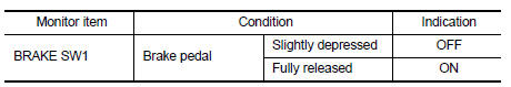
- Select “BRAKE SW1” in “DATA MONITOR” mode.
- Check “BRAKE SW1” indication under the following conditions.
 Without CONSULT
- Turn ignition switch ON.
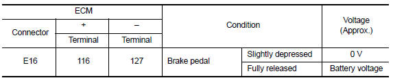
- Check the voltage between ECM harness connector terminals under the following conditions.
Is the inspection result normal? YES >> INSPECTION END
NO >> Proceed to EC-446, "Diagnosis Procedure".
Diagnosis Procedure
1.CHECK BRAKE PEDAL POSITION SWITCH POWER SUPPLY CIRCUIT
- Turn ignition switch OFF.
- Disconnect brake pedal position switch harness connector.
- Turn ignition switch ON.
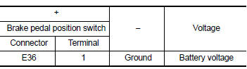
- Check the voltage between brake pedal position switch harness connector and ground.
Is the inspection result normal? YES >> GO TO 3.
NO >> GO TO 2.
2.CHECK STOP LAMP SWITCH POWER SUPPLY CIRCUIT
- Pull out #5 fuse.
- Check that the fuse is not fusing.
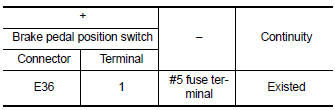
- Check the continuity between stop lamp switch harness connector and fuse terminal.
- Also check harness for short to ground and short to power.
Is the inspection result normal? YES >> Check power supply circuit for 12V battery power supply.
NO >> Repair or replace error-detected parts.
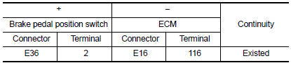
3.CHECK BRAKE PEDAL POSITION SWITCH INPUT SIGNAL CIRCUIT
- Turn ignition switch OFF.
- Disconnect ECM harness connector.
- Check the continuity between brake pedal position switch harness connector and ECM harness connector.
- Also check harness for short to ground and short to power.
Is the inspection result normal? YES >> GO TO 4.
NO >> Repair or replace error-detected parts.
4.CHECK BRAKE PEDAL POSITION SWITCH
Check brake pedal position switch. Refer to EC-447, "Component Inspection (Brake Pedal Position Switch)" Is the inspection result normal? YES >> Check intermittent incident. Refer to GI-39, "Intermittent Incident".
NO >> Replace brake pedal position switch. Refer to BR-22, "Exploded View".
Component Inspection (Brake Pedal Position Switch)
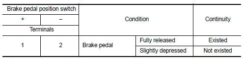
1.CHECK BRAKE PEDAL POSITION SWITCH-I
- Turn ignition switch OFF.
- Disconnect brake pedal position switch harness connector.
- Check the continuity between brake pedal position switch terminals under the following conditions.
Is the inspection result normal? YES >> INSPECTION END
NO >> GO TO 2.
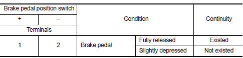
2.CHECK BRAKE PEDAL POSITION SWITCH-II
- Adjust brake pedal position switch installation. Refer to BR-15, "Adjustment".
- Check the continuity between brake pedal position switch terminals under the following conditions.
Is the inspection result normal? YES >> INSPECTION END
NO >> Replace brake pedal position switch. Refer to BR-22, "Exploded View".
 Sensor power supply 2 circuit
Description
ECM supplies a voltage of 5.0 V to some of the sensors systematically divided
into 2 groups, respectively.
Accordingly, when a short circuit develops in a sensor power source, a
ma ...
 ASCD Indicator
Component Function Check
1.CHECK ASCD INDICATOR FUNCTION
Check ASCD indicator under the following conditions.
ASCD INDICATOR
CONDITION
SPECIFICATION
CRUISE LAMP
Ig ...
Other materials:
Front door finisher
Exploded View
Front door panel
Front door finisher
Inside door handle escutcheon
Main power window and door lock/
unlock switch finisher
Door mirror corner finisher
Grommet
Clip
Pawl
Front
NOTE:
LH side shown; RH similar.
Removal and Installation
CAUTION:
When ...
P060B ECM
DTC Logic
DTC DETECTION LOGIC
DTC No.
CONSULT screen terms
(Trouble diagnosis content)
DTC detecting condition
Possible cause
P060B
CONTROL MODULE
(Internal control module A/
D processing performance)
ECM internal analog/digital conversion processing
syst ...
Fender protector
Fender protector
Fender protector : exploded view
Front fender protector
Front wind deflector
U nut
Rivet
Grommet
Front
Fender protector : removal and installation - front fender protector
REMOVAL
Remove front wheel and tire. Refer to WT-47, "Adjustment".
...
