Nissan Sentra Service Manual: Brake booster
Exploded View
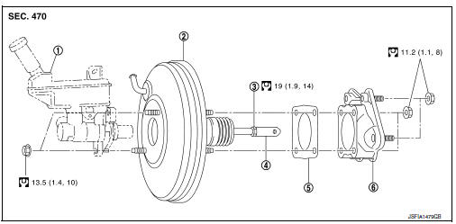
- Master cylinder assembly
- Brake booster
- Lock nut
- Clevis
- Gasket
- Spacer
Removal and installation
REMOVAL
- Remove cowl top and cowl top extension. Refer to EXT-26, "Removal and Installation".
- Remove air duct and air cleaner case. Refer to EM-25, "Removal and Installation".
- Remove brake master cylinder assembly. Refer to BR-32, "Removal and Installation".
- Remove vacuum hose from brake booster. Refer to BR-36, "Removal and Installation".
- Remove the instrument lower panel LH. Refer to IP-21, "Removal and Installation".
- Remove snap pin (1) and clevis pin (2). Refer to BR-22, "Exploded View".
- Remove nuts on brake booster and brake pedal assembly.
CAUTION:
Secure the brake booster to avoid damage to components.
- Remove brake booster and spacer.
CAUTION:
Do not deform or bend brake pipes.
NOTE:
If removing brake booster is difficult, remove clevis from brake booster.
- Remove vacuum pipe from brake booster.
- Remove spacer from brake booster.
INSTALLATION
Installation is in the reverse order of removal.
CAUTION:
- Be careful not to damage brake booster stud bolt threads. If brake booster is tilted during installation, the dash panel may damage the threads.
- Do not deform or bend the brake tubes when installing the brake booster.
- Always use a gasket between the brake booster and the spacer.
- Do not reuse the clevis pin.
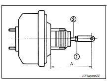
- Loosen the lock nut (1) and adjust the input rod (2) to the specified length (A). Tighten the lock nut to the specified torque.
Length (A) : Refer to BR-55, "Brake Booster".
- Perform the air bleeding. Refer to BR-17, "Bleeding Brake System".
- Check each item of brake pedal. Adjust it if the measurement value is not the standard. Refer to BR-11, "Inspection".
 Brake master cylinder
Exploded View
Reservoir cap
Oil strainer
Reservoir tank
Cylinder body
Pin
O-ring
Grommet
Apply brake fluid
PBC (Poly Butyl Cuprysil)
grease or
silicone-based grease
Remo ...
 Vacuum lines
Exploded View
Clamp
Vacuum hose (built-in check valve)
Vacuum piping
Vacuum hose
To intake manifold side
Paint mark
Stamp indicating engine direction
To brake booster
Remo ...
Other materials:
System description
COMPONENT PARTS
Component Part Location
ECM
IPDM E/R
BCM (view with combination meter
removed)
A/C auto amp. (view with A/C switch
assembly removed)
A/C switch assembly
A/C Compressor
Refrigerant pressure sensor (view
with front bumper fascia removed)
Fuse Block (J/ ...
Wiring diagram
Ipdm e/r (intelligent power distribution module engine room)
Wiring diagram
...
U1002 System comm (CAN)
DTC Logic
DTC DETECTION LOGIC
DTC
Display item
Malfunction detected condition
Possible cause
U1002
SYSTEM COMM(CAN)
When ABS actuator and electric unit (control unit) is not
transmitting or receiving CAN communication signal for 2
seconds or less.
C ...
