Nissan Sentra Service Manual: Brake master cylinder
Exploded View
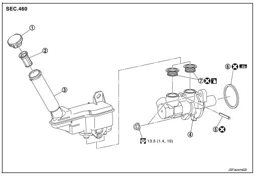
- Reservoir cap
- Oil strainer
- Reservoir tank
- Cylinder body
- Pin
- O-ring
- Grommet
 Apply brake fluid
 PBC (Poly Butyl Cuprysil)
grease or
silicone-based grease
Removal and Installation
REMOVAL
CAUTION:
- Do not spill or splash brake fluid on painted surfaces. Brake fluid may damage paint. If brake fluid is splashed on painted areas, wash it away with water immediately.
- Do not scratch the piston of master cylinder when installing/removing because the piston is exposed. Check for any dust on the piston, and wash with brake fluid if needed.
- Hold the master cylinder body when handing the master cylinder assembly. Do not hold the piston because the piston might become detached if pulled strongly.
- Refill the reservoir tank with new brake fluid “DOT 3”.
- Do not reuse drained brake fluid.
- Do not reuse master cylinder O-ring.
NOTE:
When removing components such as hoses, tubes/lines, etc., cap or plug openings to prevent fluid from spilling.
- Partially drain brake fluid. Refer to BR-17, "Drain and Refill".
- Disconnect the harness connector from the brake fluid level switch.
- Remove air duct and air cleaner case. Refer to EM-25, "Removal and Installation".
- Remove the engine room insulator and position aside.
- Separate the brake tube from master cylinder assembly with a suitable tool.
CAUTION:
Do not scratch the flare nut and the brake tube.
- Disconnect the clutch hose (if equipped).
- Remove the master cylinder assembly.
CAUTION:
- Do not deform or bend the brake tubes.
- Do not depress the brake pedal after the master cylinder assembly is removed.
- The piston of the master cylinder assembly is exposed. Do not damage the piston when removing the master cylinder.
- The piston may drop off when pulled out strongly. Do not hold the piston. Hold the cylinder body when handling the master cylinder assembly.
- Remove and discard the O-ring.
CAUTION:
Do not reuse O-ring.
INSTALLATION
Installation is in the reverse order of removal.
CAUTION:
Do not reuse O-ring.
- Apply PBC (Poly Butyl Cuprysil) grease or equivalent to the brake booster (A) when installing the master cylinder assembly to the brake booster.
- Temporarily tighten the brake tube flare nut to the master cylinder assembly by hand. Then tighten it to the specified torque.Refer to BR-25, "FRONT : Exploded View".
- Perform the air bleeding. Refer to BR-17, "Bleeding Brake System".
 Brake piping
FRONT
FRONT : Exploded View
Brake tube
ABS actuator and electric unit (control
unit)
Connector
Connector bracket
Master cylinder assembly
Brake booster
Lock plate
Brake hose
...
 Brake booster
Exploded View
Master cylinder assembly
Brake booster
Lock nut
Clevis
Gasket
Spacer
Removal and installation
REMOVAL
Remove cowl top and cowl top extension. Refer to EXT-26, ...
Other materials:
Idle speed
Inspection
1.CHECK IDLE SPEED
With CONSULT
Check idle speed in “DATA MONITOR” mode of “ENGINE” using CONSULT.
Specification : EC-486, "Idle Speed"
With GST
Check idle speed with Service $01 of GST.
Specification : EC-486, "Idle Speed"
>> INSPEC ...
Front door glass
Removal and Installation
REMOVAL
WARNING:
Before servicing, turn ignition switch OFF, disconnect both
battery terminals and wait at least three
minutes.
Do not use air tools or electric tools for servicing.
NOTE:
LH front door panel shown; RH side similar
Disconnect the battery ...
Rear drum brake
Exploded View
Cap
Bleeder valve
Piston
Spring
Boot
Piston cup
Wheel cylinder
Apply rubber grease
Apply PBC (Poly Butyl Cuprysil)
grease or silicone-based grease
Apply brake fluid
Disassembly and Assembly
DISASSEMBLY
Remove the boot from wheel cylinder. Refer t ...
