Nissan Sentra Service Manual: B terminal circuit
Description
“B” terminal circuit supplies power to charge the battery and to operate the vehicles electrical system.
Diagnosis procedure
Regarding wiring diagram information. Refer to chg-9, "wiring diagram".
1.Check “b” terminal connection
- Turn ignition switch off.
- Check if “b” terminal is clean and tight.
Is the inspection result normal? Yes >> go to 2.
No >> repair terminal “b” connection. Confirm repair by performing complete charging system test using the exp-800 ni or gr8-1200 ni (if available). Refer to applicable instruction manual for proper testing procedures.
2.Check “b” terminal circuit
Check voltage between generator “b” terminal and ground.
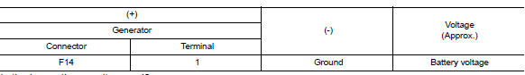
Is the inspection result normal? Yes >> go to 3.
No >> check harness for open between generator and fusible link.
3.Check “b” terminal connection (voltage drop test)
- Start engine, then engine running at idle and warm.
- Check voltage between battery positive terminal and generator connector “b” terminal.
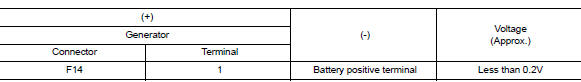
Is the inspection result normal? YES >> “B” terminal circuit is normal. Refer to CHG-14, "Work Flow (With EXP-800 NI or GR8-1200 NI)" or CHG-17, "Work Flow (Without EXP-800 NI or GR8-1200 NI)".
NO >> Check harness between battery and generator for continuity.
 Power generation voltage variable control system operation inspection
Diagnosis Procedure
Regarding wiring diagram information. Refer to chg-9, "wiring diagram".
Caution:
When performing this inspection, always use a charged battery that has
completed the ...
 L terminal circuit (open)
Description
The “L” terminal circuit controls the charge warning lamp. The charge warning
lamp turns ON when the ignition
switch is set to ON or START. When the generator is providing su ...
Other materials:
Daytime light system inoperative
Description
The daytime light system is inoperative even though the combination switch
(lighting and turn signal switch)
and parking brake switch are in the normal setting, also whenever engine is
operating.
Diagnosis procedure
1.Check daytime light operation
Perform bcm(headlamp) daytim ...
Starter motor drive control
STARTER MOTOR DRIVE CONTROL : System Description
SYSTEN DIAGRAM
*1: CVT models
*2: M/T models
INPUT/OUTPUT SIGNAL CHART
Sensor
Input signal to ECM
ECM function
Actuator
Crankshaft position sensor (POS)
Engine speed
Piston position
Starter ...
BCM branch line circuit
Diagnosis procedure
1.Check connector
Turn the ignition switch off.
Disconnect the battery cable from the negative terminal.
Check the terminals and connectors of the bcm for damage, bend and loose
connection (unit side and
connector side).
Is the inspection result normal?
YES > ...
