Nissan Sentra Service Manual: L terminal circuit (open)
Description
The “L” terminal circuit controls the charge warning lamp. The charge warning lamp turns ON when the ignition switch is set to ON or START. When the generator is providing sufficient voltage with the engine running, the charge warning lamp turns OFF. If the charge warning lamp illuminates with the engine running, a malfunction is indicated.
Diagnosis procedure
Regarding Wiring Diagram information. Refer to CHG-9, "Wiring Diagram".Đ Ńš
1.Check “l” terminal connection
- Turn ignition switch off.
- Check if “l” terminal is clean and tight.
Is the inspection result normal? Yes >> go to 2.
No >> repair “l” terminal connection. Confirm repair by performing complete charging system test using exp-800 ni or gr8-1200 ni (if available). Refer to applicable instruction manual for proper testing procedures.
2.Check “l” terminal circuit (open)
- Disconnect the generator connector.
- Apply ground to generator harness connector terminal.
- Check condition of the charge warning lamp with the ignition switch in the on position.
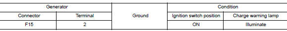
Does it illuminate? YES >> “L” terminal circuit is normal. Refer to CHG-14, "Work Flow (With EXP-800 NI or GR8-1200 NI)" or CHG-17, "Work Flow (Without EXP-800 NI or GR8-1200 NI)".
NO >> GO TO 3.
3.Check harness continuity (open circuit)
- Disconnect the battery cable from the negative terminal.
- Disconnect the combination meter connector.
- Check continuity between generator harness connector and combination meter harness connector.
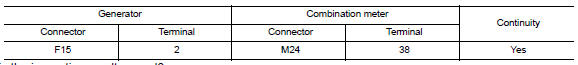
Is the inspection result normal? Yes >> go to 4.
No >> repair or replace the harness or connectors.
4.Check power supply circuit
- Connect the battery cable to the negative terminal.
- Check voltage between combination meter harness connector and ground.
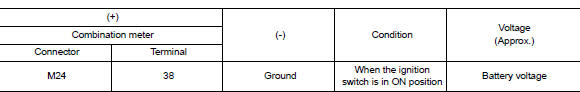
Is the inspection result normal? Yes >> replace the combination meter. Refer to mwi-77, "removal and installation".
No >> repair or replace the harness or connectors.
 B terminal circuit
Description
“B” terminal circuit supplies power to charge the battery and to operate the
vehicles electrical system.
Diagnosis procedure
Regarding wiring diagram information. Refer to c ...
 L terminal circuit (short)
Description
The terminal “l” circuit controls the charge warning lamp. The charge warning
lamp turns on when the ignition
switch is set to on or start. When the generator is providing s ...
Other materials:
Multiport fuel injection system
MULTIPORT FUEL INJECTION SYSTEM : System
Description
SYSTEM DIAGRAM
*1: ECM determines the start signal status by the signals of engine speed and
battery voltage.
*2: M/T models
*3: CVT models
*4: This sensor is not used to control the engine system under normal
conditions.
SYSTEM DES ...
Wiring diagram
CVT Control system
Wiring Diagram
CVT Shift lock system
Wiring Diagram
...
Rear disc brake
Brake Burnishing
CAUTION:
Burnish contact surfaces between brake pads and disc rotor
according to the following procedure
after refinishing the disc rotor, replacing brake pads or if a soft pedal
occurs at very low mileage.
Be careful of vehicle speed. Brakes do not operate firmly/sec ...
