Nissan Sentra Service Manual: Power generation voltage variable control system operation inspection
Diagnosis Procedure
Regarding wiring diagram information. Refer to chg-9, "wiring diagram".
Caution:
When performing this inspection, always use a charged battery that has completed the battery inspection.
(When the charging rate of the battery is low, the response speed of the voltage change will become slow. This can cause an incorrect inspection.)
1.Check ecm (consult)
Perform ecm self-diagnosis with consult. Refer to ec-66, "consult function".
Self-diagnostic results content
No malfunction detected>> go to 2.
Malfunction detected>> check applicable parts, and repair or replace corresponding parts.
2.Check operation of power generation voltage variable control system
- Connect consult and start the engine.
- The selector lever is in “p” or “n” position and all of the electric loads and a/c, etc. Are turned off.
- Select “alternator duty” in “active test” of “engine”, and then check the value of “battery volt” monitor when duty value of “duty” is set to 40.0 %.
“Battery volt” 2 seconds after setting the duty value of “alternator duty” to 40.0 % : 12 - 13.6 V
- Check the value of “battery volt” monitor when duty value of “duty” is set to 80.0%.
“Battery volt” 20 seconds after setting the duty value of “alternator duty” to 80.0 % : +0.5 V or more against the value of “battery volt” monitor when duty value is 40.0 %
Is the inspection result normal? Yes >> inspection end.
No >> go to 3.
3.Check ipdm e/r (consult)
Perform ipdm e/r self-diagnosis with consult. Refer to pcs-10, "consult function (ipdm e/r)"
(with intelligent key system) or pcs-38, "consult function (ipdm e/r)" (without intelligent key system).
Is the inspection result normal? No malfunction detected>> go to 4.
Malfunction detected>> check applicable parts, and repair or replace corresponding parts.
4.Check harness between generator and ipdm e/r
- Turn ignition switch off.
- Disconnect generator connector and ipdm e/r connector.
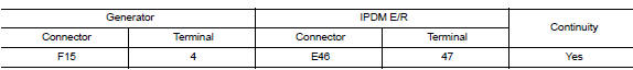
- Check continuity between generator harness connector and ipdm e/r harness connector.
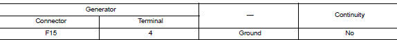
- Check continuity between generator harness connector and ground.
Is the inspection result normal? Yes >> replace ipdm e/r. Refer to pcs-30, "removal and installation".
No >> repair harness or connectors between ipdm e/r and generator.
 Charging system preliminary inspection
Diagnosis Procedure
1.CHECK BATTERY TERMINALS CONNECTION
Check if battery terminals are clean and tight.
Is the inspection result normal?
YES >> GO TO 2.
NO >> Repair battery term ...
 B terminal circuit
Description
“B” terminal circuit supplies power to charge the battery and to operate the
vehicles electrical system.
Diagnosis procedure
Regarding wiring diagram information. Refer to c ...
Other materials:
Dlc branch line circuit
Diagnosis procedure
1.Check connector
Turn the ignition switch off.
Disconnect the battery cable from the negative terminal.
Check the terminals and connectors of the data link connector for
damage, bend and loose connection
(connector side and harness side).
Is the inspection resul ...
Squeak and rattle trouble diagnoses
Work Flow
Customer interview
Interview the customer if possible, to determine the conditions that exist
when the noise occurs. Use the diagnostic
worksheet during the interview to document the facts and conditions when the
noise occurs and any
customer's comments; refer to rf-37, "d ...
The braking distance is long
Diagnosis Procedure
CAUTION:
The stopping distance on slippery road surfaces might be
longer with the ABS operating than when
the ABS is not operating.
1.CHECK ABS FUNCTION
Turn ignition switch OFF.
Disconnect ABS actuator and electric unit (control unit)
connector to deactivate ...
