Nissan Sentra Service Manual: Transverse link
Exploded View
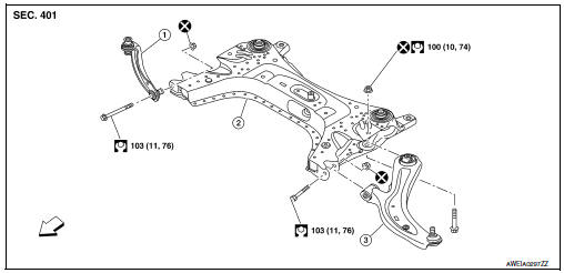
- Upper link
- Front suspension member
- Transverse link
 Front
Front
Removal and Installation
REMOVAL
- Remove the wheel and tire using power tool. Refer to WT-47, "Exploded View".
- Remove the nut and bolt from the lower ball joint. Disconnect the
transverse link from steering knuckle.
Refer to FAX-8, "Exploded View".
- Remove the nuts and bolts and disconnect the transverse link from the suspension member.
- Inspect the components. Refer to FSU-10, "Inspection".
INSTALLATION
Installation is in the reverse order of removal.
CAUTION:
Do not reuse the transverse link nuts.
- Perform the final tightening of the nuts and bolts under unladen conditions with the tires on level ground.
- Complete the inspection. Refer to FSU-10, "Inspection".
Inspection
INSPECTION AFTER REMOVAL
Check the following items, and replace the parts if necessary.
Transverse Link
- Check the transverse link and bushing for deformation, cracks or damage.
- Check the ball joint boot for cracks or other damage, and also for grease leaks.
Swing Torque
- Move the ball joint at least ten times by hand to check for smooth movement with no binding.
- Hook the Tool (A) on the on ball joint (B). Confirm the measurement value is within specifications when the ball joint begins moving.
Tool number : — (J-44372)
Swing torque : Refer to FSU-23, "Ball Joint".
Measurement on spring balance : Refer to FSU-23, "Ball Joint"
- If swing torque exceeds standard range, replace the transverse link.
Axial End Play
- Move the ball joint at least ten times by hand to check for smooth movement.
- Move the tip of the ball joint in the axial direction to check for looseness.
Axial end play : Refer to FSU-23, "Ball Joint".
- If the axial end play exceeds the standard value, replace the transverse link.
INSPECTION AFTER INSTALLATION
- Check the neutral position of the steering angle sensor. Refer to BRC-54, "Work Procedure".
- Check the wheel alignment. Refer to FSU-6, "Inspection".
 Front coil spring and strut
Exploded View
Piston rod lock nut
Strut mount insulator
Strut mount bearing
Bound bumper
Coil spring
Lower rubber seat
Strut
Steering knuckle
Front
Removal and Installation ...
 Front stabilizer
Exploded View
Stabilizer bar
Stabilizer clamp
Stabilizer bushing
Stabilizer connecting rod
Front coil spring and strut
Front suspension member
Front
Removal and Installation
RE ...
Other materials:
Symptom diagnosis
Nissan vehicle immobilizer systemnats
symptoms
Symptom Table
Note:
Before performing the diagnosis in the following table, check
“SEC-171, "Work Flow"”.
Check that vehicle is under the condition shown in “Conditions of
vehicle” before starting diagnosis, ...
Daytime light system inoperative
Description
The daytime light system is inoperative even though the combination switch
(lighting and turn signal switch)
and parking brake switch are in the normal setting, also whenever engine is
operating.
Diagnosis procedure
1.Check daytime light operation
Perform bcm(headlamp) daytim ...
Fuel efficient driving tips
Follow these easy-to-use Fuel Efficient Driving
Tips to help you achieve the most fuel economy
from your vehicle.
Use Smooth Accelerator and Brake
Pedal Application
Avoid rapid starts and stops
Use smooth, gentle accelerator and
brake application whenever possible
Maintain consta ...
