
Nissan Sentra Service Manual: Front coil spring and strut
Exploded View
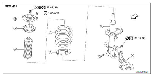
- Piston rod lock nut
- Strut mount insulator
- Strut mount bearing
- Bound bumper
- Coil spring
- Lower rubber seat
- Strut
- Steering knuckle
 Front
Front
Removal and Installation
REMOVAL
- Remove the wheel and tire using power tool. Refer to WT-47, "Exploded View".
- Remove the lock plate from the front coil spring and strut and reposition the brake hose. Refer to BR-25, "FRONT : Exploded View".
- Disconnect the stabilizer connecting rod from the front coil spring and strut. Refer to FSU-12, "Removal and Installation".
- Remove the wheel sensor bolt. Position the wheel sensor and the wheel sensor harness aside. Refer to BRC-106, "FRONT WHEEL SENSOR : Removal and Installation".
- Use a jack to support the transverse link and the steering knuckle.
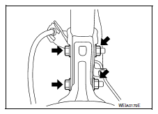
- Remove the lower strut nuts and bolts (
 ).
).
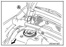
- Remove the grommet (A) from the cowl top cover.
 : Front
- Access 1 upper strut bolt through the grommet hole.
- Remove the upper strut bolts from the strut mount insulator (1).
- Remove the front coil spring and strut.
- Inspect the components. Refer to FSU-21, "Inspection".
INSTALLATION
Installation is in the reverse order of removal.
CAUTION:
Do not reuse piston rod lock nut or strut nuts.
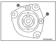
- Install the front coil spring and strut with the identification mark (A) of the strut mount insulator facing toward the front of the vehicle and the arrow (B) facing the outboard side.
NOTE:
The identification mark "0" shows the (RH) strut mount insulator and "1" shows the (LH).
- Perform the final tightening of the bolts and nuts under unladen conditions with the tires on level ground.
- Complete the inspection. Refer to FSU-21, "Inspection".
- After replacing the strut, always follow the disposal procedure to discard the old strut. Refer to FSU-22, "Disposal".

 Transverse link
Exploded View
Upper link
Front suspension member
Transverse link
Front
Removal and Installation
REMOVAL
Remove the wheel and tire using power tool. Refer to WT-47, "Explode ...
Other materials:
Moonroof (if so equipped)
Power moonroof
The moonroof will only operate when the ignition
switch is placed in the ON position. The power
moonroof is operational for a period of time, even
if the ignition switch is placed in the ACC or OFF
position. If the driver’s door or the front passenger’s
door is opened du ...
Troubleshooting guide
The system should respond correctly to all voice
commands without difficulty. If problems are encountered,
try the following solutions.
Where the solutions are listed by number, try
each solution in turn, starting with number 1, until
the problem is resolved.
Symptom
Solution
...
Oil seal
Valve oil seal : Removal and Installation
REMOVAL
Rotate crankshaft, and set piston whose valve oil seal is to be removed
to TDC. This will prevent valve
from dropping into cylinder.
CAUTION:
When rotating crankshaft, be careful to avoid scarring front cover with
timing chain.
Re ...
