Nissan Sentra Service Manual: Steering gear and linkage
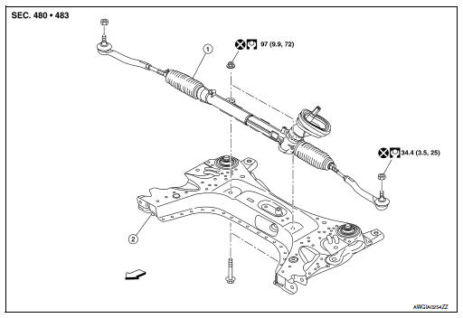
Exploded View
REMOVAL
-
Steering gear assembly
-
Front suspension member
 Front
Front
Removal and Installation
REMOVAL
-
Set steering wheel to the straight-ahead position.
-
Remove floor cover (1).
-
Lower shaft assembly (2).
-
Remove the lower shaft assembly bolt and position the lower shaft assembly out of the way. Refer to ST- 12, "Removal and Installation".
CAUTION:
-
Spiral cable may be cut if steering wheel turns while separating steering column assembly and steering gear assembly. Always fix the steering wheel using string to avoid turning.
-
Place a matching mark on both intermediate shaft and steering gear assembly before removing intermediate shaft.
-
Remove wheels and tires using power tool. Refer to WT-47, "Adjustment".
-
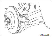
Remove steering outer socket from steering knuckle so as not to damage ball joint boot using Tool.
Tool number : HT72520000 (J-25730-A)
CAUTION:
Temporarily tighten the nut to prevent damage to threads and to prevent the Tool from a sudden drop.
-
Remove front suspension member. Refer to FSU-16, "Removal and Installation".
-
Remove steering gear assembly from front suspension member.
INSTALLATION
Installation is in the reverse order of removal.
CAUTION:
Spiral cable may be cut if steering wheel turns while separating steering column assembly and steering gear assembly. Always fix the steering wheel using string to avoid turning.
-
Perform final tightening of nuts and bolts on each part under unladen conditions with tires on level ground when removing steering gear assembly.
-
Check wheel alignment. Refer to FSU-7, "Adjustment".
-
Rotate steering wheel to check for decentered condition, binding, noise or excessive steering effort.
-
Do not reuse steering outer socket nut and steering gear assembly nut.
-
Perform neutral position steering angle adjustment. Refer to BRC-54, "Work Procedure".
 Steering column
Exploded View
Steering column assembly
Slide plates
lower shaft assembly
Removal and Installation
REMOVAL
CAUTION:
While removing the steering column assembly, do not ...
 Unit disassembly and assembly
Steering gear and linkage
Exploded View
Outer socket
Boot clamp (small diameter)
Boot
Boot clamp (large diameter)
Inner socket
Gear housing assembly
Disassembl ...
Other materials:
Towing your vehicle
When towing your vehicle, all State (Provincial in
Canada) and local regulations for towing must be
followed. Incorrect towing equipment could damage
your vehicle. Towing instructions are available
from a NISSAN dealer. Local service operators
are generally familiar with the applicable laws
an ...
Exterior front
Engine hood
Windshield wiper and washer switch,
Windshield
Moonroof (if so equipped)
Power windows
Door locks, keyfob, keys, NISSAN
Intelligent Key® (if so equipped)
Mirrors
Tire pressure
Flat tire
Tire chains
Replacing bulbs
Headlight and turn signal switch, LED
he ...
The steering switch (meter control switch) is inoperative
Description
If any of the following malfunctions is found for the steering switch (meter
control switch) operation.
All switches are inoperative
The specified switch cannot be operated
Diagnosis procedure
1.Check steering switch signal circuit
Check the steering switch signal circuit. ...
