Nissan Sentra Service Manual: Steering column
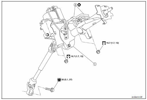
Exploded View
-
Steering column assembly
-
Slide plates
-
lower shaft assembly
Removal and Installation
REMOVAL
CAUTION:
-
While removing the steering column assembly, do not unlock the tilt lever.
-
Do not impact on the axis when removing steering column assembly.
-
Be careful when removing steering column assembly from the vehicle because it is heavy.
-
Keep steering column assembly away from magnetic sources.
-
Do not disassemble steering column assembly, it is all one piece.
-
While removing the steering column assembly, do not move the steering gear assembly.
-
When removing the steering column assembly, be careful not to allow the lower shaft assembly to turn.
-
Set steering wheel to the straight-ahead position.
-
Place the tilt to the lowest level.
CAUTION:
Securely lock the tilt lever.
-
Remove instrument lower panel LH. Refer to IP-21, "Removal and Installation".
-
Remove driver air bag module. Refer to SR-12, "Removal and Installation".
-
Remove steering wheel. Refer to ST-10, "Removal and Installation".
-
Remove steering column cover. Refer to IP-16, "Removal and Installation".
-
Remove spiral cable. Refer to SR-16, "Removal and Installation".
-
Remove combination switch.
-
Disconnect key interlock cable (if equipped). Refer to TM-260, "Removal and Installation".
-
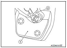
Remove hole cover (1).
-
Lower shaft assembly (2).
-
Remove lower side bolt of lower shaft assembly.
-
Disconnect each harness connector and harness clips installed to steering column assembly.
-
Disconnect EPS control unit harness connectors.
-
Remove the steering column assembly nuts.
CAUTION:
When removing the steering column assembly nuts, be careful not to drop the steering column assembly.
-
Remove the steering column.
-
Remove EPS control unit. Refer to STC-39, "Removal and Installation".
INSTALLATION
CAUTION:
-
Do not impact on the axis when removing steering column assembly.
-
When installing the steering column cover, check that the vehicle harness is not stuck in the cover.
Installation is in the reverse order of removal.
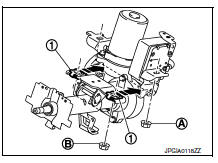
-
After tightening nut (A) of the steering column assembly, press in slide plate (outer and inner) (1) to tighten nut (B).
CAUTION:
-
Do not reuse slide plate.
-
The slide plate must be securely pressed in before tightening the nut of slide plate.
Lower shaft bolt is directional. Refer to ST-12, "Exploded View".
CAUTION:
Do not reuse lower shaft assembly bolt.
-
After installing steering column assembly, perform self-diagnosis with CONSULT to ensure correct operation.
Refer to STC-10, "CONSULT Function".
-
Perform inspection after installation. Refer to ST-7, "Inspection".
 Steering wheel
Exploded View
Driver air bag module
Steering wheel
Steering column assembly
Removal and Installation
REMOVAL
NOTE:
When reconnecting spiral cable, fix cable with a tape so t ...
 Steering gear and linkage
Exploded View
REMOVAL
Steering gear assembly
Front suspension member
Front
Removal and Installation
REMOVAL
Set steering wheel to the straight-ahead position.
Remove ...
Other materials:
Seat belts
The seat belts can be cleaned by wiping them
with a sponge dampened in a mild soap solution.
Allow the belts to dry completely in the shade
before using them. See “Seat belt maintenance”
in the “Safety – Seats, seat belts and supplemental
restraint system” section of this manual.
...
U1001 can comm circuit
Description
CAN (Controller Area Network) is a serial communication line for real time
application. It is an on-vehicle multiplex
communication line with high data communication speed and excellent error
detection ability. Many electronic
control units are equipped onto a vehicle, and each co ...
Precautions when starting and driving
WARNING
Do not leave children or adults who
would normally require the assistance
of others alone in your vehicle. Pets
should also not be left alone. They
could accidentally injure themselves or
others through inadvertent operation of
the vehicle. Also, on hot, su ...
