Nissan Sentra Service Manual: Unit disassembly and assembly
Steering gear and linkage
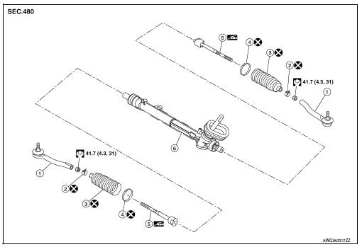
Exploded View
-
Outer socket
-
Boot clamp (small diameter)
-
Boot
-
Boot clamp (large diameter)
-
Inner socket
-
Gear housing assembly
Disassembly and Assembly
DISASSEMBLY
-
Loosen outer socket lock nut, and remove outer socket.
CAUTION:
When loosening lock nut, be sure to fix outer socket with a wrench or an equivalent.
-
Remove boot clamps, and then remove boot from inner socket.
CAUTION:
-
Do not damage inner socket part and gear housing part of steering gear assembly when removing boot. steering gear assembly must be replaced if steering gear assembly are damaged because it may cause foreign material interfusion.
-
Do not reuse boot clamps.
-
Remove inner socket.
ASSEMBLY
-
Apply recommended grease to inner socket (A) of gear housing assembly, and install boot to gear housing assembly.
Use Genuine Lithium Soap, Autorex A (manufactured by Kyodo yushi) or equivalent.
CAUTION:
Do not reuse boot.
Grease application position (Reference) (B) : 10 mm (0.39 in)
-
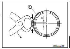
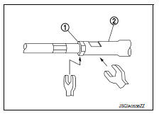
Install boot clamp (large diameter) (1) to boot using Tool.
CAUTION:
-
Do not reuse boot clamp (large diameter).
-
Install boot clamp (large diameter) securely to boot groove, and crimp it so as to have clearance (B) of 3 mm (0.12 in) or less as shown.
Tool number (A) : KV40107300 ( — )
-
Install boot clamp (small diameter) to boot.
CAUTION:
Do not reuse boot clamp (small diameter).
-
Adjust inner socket to standard length (L), and then tighten outer socket lock nut (1) to the specified torque. Check length again after tightening lock nut.
(L) : Refer to ST-19, "Power Steering Gear".
CAUTION:
-
When tightening the outer socket lock nut (1), be sure to fix outer socket (2) with suitable tool to prevent the ball joint from getting contact with the knuckle.
-
Adjust toe-in after this procedure. The length achieved after toe-in adjustment is not necessary the above value.
 Steering gear and linkage
Exploded View
REMOVAL
Steering gear assembly
Front suspension member
Front
Removal and Installation
REMOVAL
Set steering wheel to the straight-ahead position.
Remove ...
 Service data and specifications (SDS)
Steering Wheel
Steering Angle
Steering Column
STEERING COLUMN LENGTH
TILT MECHANISM OPERATING RANGE
Power Steering Gear
STEERING OUTER SOCKET AND INNER SOCKET
RACK STROKE
...
Other materials:
ID registration cannot be completed
Diagnosis Procedure
NOTE:
The Signal Tech II Tool (J-50190) can be used to perform the following
functions. Refer to the Signal Tech II
User Guide for additional information.
Activate and display TPMS transmitter IDs
Display tire pressure reported by the TPMS transmitter
Read TPMS DTCs
...
Interior lights
The interior light can be turned ON regardless
of door position. The light will go off after
a period of time unless the ignition switch is
placed in the ON position when any door is
opened.
The interior lights can be set to operate
when the doors are opened. To turn off the
int ...
Precaution for Supplemental Restraint System (SRS) "AIR BAG" and "SEAT BELT
PRE-TENSIONER"
The Supplemental Restraint System such as –≤–Ç—öAIR BAG–≤–Ç—ú and –≤–Ç—öSEAT BELT
PRE-TENSIONER–≤–Ç—ú, used along
with a front seat belt, helps to reduce the risk or severity of injury to the
driver and front passenger for certain
types of collision. Information necessary to service the system ...
