Nissan Sentra Service Manual: S connector circuit
Description
The starter motor magnetic switch is supplied with power when the ignition switch is turned to the START position while the selector lever is in the P (Park) or N (Neutral) position (CVT Models) or the clutch pedal is depressed (M/T Models).
Diagnosis Procedure
Regarding Wiring Diagram information, refer to STR-10, "Wiring Diagram" (with Intellignet Key system) or STR-15, "Wiring Diagram" (without Intelligent Key system).
CAUTION:
Perform diagnosis under the condition that engine cannot start by the following procedure.
- Remove fuel pump fuse.
- Crank or start the engine (where possible) until the fuel pressure is released.
1.CHECK “S” CONNECTOR CIRCUIT
- Turn ignition switch OFF.
- Disconnect starter motor connector.
- Shift selector lever to “P” (Park) or “N” (Neutral) position (CVT Models) or the clutch pedal is depressed (M/T Models).
- Check voltage between starter motor harness connector F28 and ground.
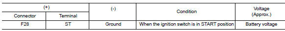
Is the inspection result normal? YES >> “S” circuit is OK. Further inspection is necessary. Refer to STR-20, "Work Flow (With GR8-1200 NI)" or STR-24, "Work Flow (Without GR8-1200 NI)".
NO >> GO TO 2.
2.CHECK HARNESS CONTINUITY (OPEN CIRCUIT)
- Disconnect IPDM E/R connector.
- Check continuity between starter motor harness connector F28 and the IPDM E/R harness connector E44.
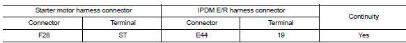
Is the inspection result normal? YES >> Further inspection is necessary. Refer to STR-20, "Work Flow (With GR8-1200 NI)" or STR-24, "Work Flow (Without GR8-1200 NI)".
NO >> Repair or replace the harness or connectors.
 B terminal circuit
Description
Terminal “B” is constantly supplied with battery power.
Diagnosis Procedure
Regarding Wiring Diagram information, refer to STR-10, "Wiring Diagram" (with
Intellig ...
 Symptom diagnosis
Starting system
Symptom table
Symptom
Reference
No normal cranking
Refer to STR-20, "Work Flow (With GR8-1200 NI)" or
STR-24, "Work Flow (Without GR8-1200 NI ...
Other materials:
Removal and installation
Power socket
Removal and installation
Front console power socket
Removal
Remove the cvt/mt shift selector finisher. Refer to ip-14, "exploded
view".
Remove cap from the front console power socket.
Remove the screws (a) and the storage bin (1).
Disconnect the harness ...
Parking, license plate and tail
lamps are not turned on
Description
The parking, license plate and tail lamps do not turn on in with any lighting
switch setting.
Diagnosis procedure
1.Combination switch (lighting and turn signal switch) inspection
Check the combination switch (lighting and turn signal switch). Refer to
BCS-72, "Symptom Table ...
Fuel injector and fuel tube
Exploded View
Bracket
Fuel tube bracket
Fuel feed tube
Quick connector cap
Fuel tube
O-ring (black)
Fuel injector
O-ring (green)
Injector clip
CAUTION:
Do not remove or disassemble parts unless instructed.
Removal and Installation
WARNING:
Put a “CAUTION: FLAM ...
