Nissan Sentra Service Manual: B terminal circuit
Description
Terminal “B” is constantly supplied with battery power.
Diagnosis Procedure
Regarding Wiring Diagram information, refer to STR-10, "Wiring Diagram" (with Intelligent Key system) or STR-15, "Wiring Diagram" (without Intelligent Key system).
CAUTION:
Perform diagnosis under the condition that the engine cannot start by the following procedure.
- Remove fuel pump fuse.
- Crank or start the engine (where possible) until the fuel pressure is released.
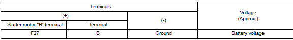
1.CHECK “B” TERMINAL CIRCUIT
- Turn ignition switch OFF
- Check that starter motor B” terminal connection is clean and tight.
- Check voltage between starter motor connector F27 and ground.
Is the inspection result normal? YES >> GO TO 2.
NO >> Check harness between battery and starter motor for open circuit.
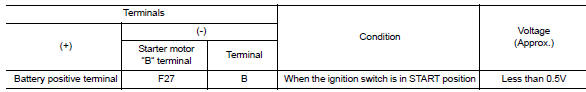
2.CHECK BATTERY CABLE CONNECTION STATUS (VOLTAGE DROP TEST)
- Shift selector lever to P (Park) or N (Neutral) position (CVT Models) or the clutch pedal is depressed (M/T Models).
- Check voltage between battery positive terminal and starter motor B terminal.
Is the inspection result normal? YES >> GO TO 3.
NO >> Check harness between the battery and starter motor for continuity.
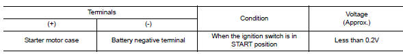
3.CHECK GROUND CIRCUIT STATUS (VOLTAGE DROP TEST)
- Shift selector lever to P (Pack) or N (Neutral) position (CVT Models) or the clutch pedal is depressed (M/T Models).
- Check voltage between starter motor case and battery negative terminal.
Is the inspection result normal? YES >> “B” terminal circuit is OK. Further inspection is necessary. Refer to STR-20, "Work Flow (With GR8-1200 NI)" or STR-24, "Work Flow (Without GR8-1200 NI)".
NO >> Check the starter motor case to engine mounting for high resistance.

 S connector circuit
Description
The starter motor magnetic switch is supplied with power when the ignition
switch is turned to the START position
while the selector lever is in the P (Park) or N (Neutral) position (C ...
Other materials:
Precaution
Precaution for supplemental restraint system (srs) "air bag" and "seat
belt
pre-tensioner"
The supplemental restraint system such as “air bag” and “seat belt pre-tensioner”,
used along
with a front seat belt, helps to reduce the risk or severity of inju ...
Moonroof motor assembly
Exploded view
Headlining
Sun visor
Moonroof motor assembly
Front
Removal and installation
REMOVAL
Close the glass lid.
Remove the map lamp. Refer to INL-52, "Removal and Installation".
Remove the moonroof motor bolts (A).
Front
Disconnect the harness connec ...
Ipdm-e branch line circuit
Diagnosis Procedure
1.Check connector
Turn the ignition switch off.
Disconnect the battery cable from the negative terminal.
Check the terminals and connectors of the ipdm e/r for damage, bend and
loose connection (unit side
and connector side).
Is the inspection result normal?
Yes ...
