Nissan Sentra Service Manual: Power supply and ground circuit
Diagnosis Procedure
1.CHECK FUSE
Check that the following fuse is not fusing.
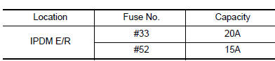
Is the fuse fusing? YES >> Replace the fuse after repairing the applicable circuit.
NO >> GO TO 2.
2.CHECK GROUND CONNECTION
- Turn ignition switch OFF
- Check ground connection E9 and E15. Refer to GI-42, "Circuit Inspection".
Is the inspection result normal? YES >> GO TO 3.
NO >> Repair or replace ground connection.
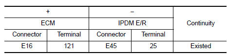
3.CHECK ECM GROUND CIRCUIT
- Disconnect ECM harness connectors.
- Check the continuity between ECM harness connector and ground.
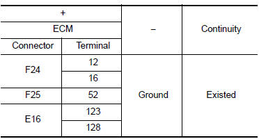
Is the inspection result normal? YES >> GO TO 4.
NO >> Repair or replace error-detected parts.
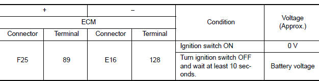
4.CHECK ECM POWER SUPPLY (MAIN)-1
- Reconnect ECM harness connector.
- Turn ignition switch ON.
- Check the voltage between ECM harness connector terminals.
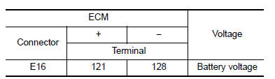
Is the inspection result normal? YES >> GO TO 5.
NO >> GO TO 6.
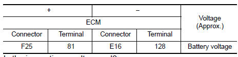
5.CHECK ECM POWER SUPPLY (MAIN)-2
- Turn ignition switch OFF and wait at least 10 seconds.
- Check the voltage between ECM harness connector terminals as per the following.
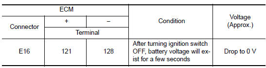
Is the inspection result normal? YES >> GO TO 9.
NO >> GO TO 7.
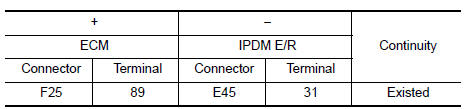
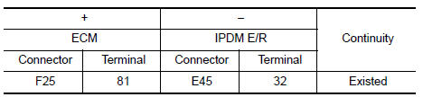
6.CHECK ECM POWER SUPPLY (MAIN) CIRCUIT
- Turn ignition switch OFF.
- Disconnect ECM harness connectors.
- Disconnect IPDM E/R harness connector.
- Check the continuity between ECM harness connector and IPDM E/R harness connector.
- Also check harness for short to ground.
Is the inspection result normal? YES >> Perform the trouble diagnosis for power supply circuit.
NO >> Repair or replace error-detected parts.
7.CHECK ECM RELAY CONTROL SIGNAL
Check the voltage between ECM harness connector terminals as per the following.
Is the inspection result normal? YES >> Check Intermittent incident. Refer to GI-39, "Intermittent Incident".
NO >> GO TO 8.
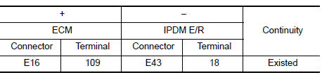
8.CHECK ECM RELAY CONTROL SIGNAL CIRCUIT
- Turn ignition switch OFF
- Disconnect ECM harness connector.
- Disconnect IPDM E/R harness connector
- Check the continuity between ECM harness connector and IPDM E/R harness connector.
- Also check harness for short to ground and to power.
Is the inspection result normal? YES >> Replace IPDM E/R. Refer to PCS-58, "Removal and Installation" (with intelligent key), PCS-58, "Removal and Installation" (without intelligent key).
NO >> Repair or replace error-detected parts.
9.CHECK IGNITION SWITCH SIGNAL
- Turn ignition switch ON.
- Check the voltage between ECM harness connector terminals.
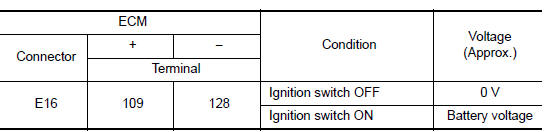
Is the inspection result normal? YES >> GO TO 11.
NO >> GO TO 10.
10.CHECK IGNITION SWITCH SIGNAL CIRCUIT
- Turn ignition switch OFF.
- Disconnect ECM harness connector.
- Disconnect IPDM E/R harness connector.
- Check the continuity between ECM harness connector and IPDM E/R harness connector.
- Also check harness for short to ground and to power.
Is the inspection result normal? YES >> Perform the trouble diagnosis for power supply circuit.
NO >> Repair or replace error-detected parts.
11.CHECK ECM POWER SUPPLY (BACK-UP)
Check the voltage between ECM harness connector terminals.
Is the inspection result normal? YES >> Check Intermittent Incident. Refer to GI-39, "Intermittent Incident".
NO >> GO TO 12.
12.CHECK ECM POWER SUPPLY (BACK-UP) CIRCUIT
- Turn ignition switch OFF.
- Disconnect ECM harness connector.
- Disconnect IPDM E/R harness connector.
- Check the continuity between ECM harness connector and IPDM E/R harness connector.
- Also check harness for short to ground.
Is the inspection result normal? YES >> Perform the trouble diagnosis for power supply circuit.
NO >> Repair or replace error-detected parts.
 Trouble diagnosis - specification
value
Trouble diagnosis - specification
value
Description
The specification (SP) value indicates the tolerance of the value that is
displayed in “SPEC” of “DATA MONITOR”
mode of CONSULT during normal operation of the Engin ...
 U0101 can comm circuit
Description
CAN (Controller Area Network) is a serial communication line for real time
application. It is an on-vehicle multiplex
communication line with high data communication speed and excellen ...
Other materials:
Heater operation
This mode is used to direct heated air to the foot
outlets. Some air also flows from the defrost
outlets and the side vent outlets.
Press the button to the OFF
position
for normal heating.
Press the air flow control
button.
Turn the fan control dial to the desired position.
Tur ...
Positive crankcase ventilation
Inspection
1.CHECK PCV VALVE
With engine running at idle, remove PCV valve from rocker cover. A
properly working valve makes a hissing noise as air passes through
it. A strong vacuum should be felt immediately when a finger is
placed over valve inlet.
Is the inspection result normal?
YES &g ...
NISSAN Voice Recognition System (if so
equipped)
The NISSAN Voice Recognition system allows
hands-free operation of the systems equipped on
this vehicle, such as the phone and navigation
systems.
To operate NISSAN Voice Recognition, press
the button located on the steering
wheel.
When prompted, speak the command for the
system you wi ...
