Nissan Sentra Service Manual: Power supply and ground circuit
Bcm (body control system) (with intelligent key system)
BCM (BODY CONTROL SYSTEM) (WITH INTELLIGENT KEY SYSTEM) : Diagnosis Procedure
Regarding Wiring Diagram information, refer to BCS-51, "Wiring Diagram".
1.CHECK FUSES AND FUSIBLE LINK
Check that the following fuses and fusible link are not blown.

Is the fuse blown? YES >> Replace the blown fuse or fusible link after repairing the affected circuit.
NO >> GO TO 2.
2.Check power supply circuit
- Disconnect BCM connector M85.
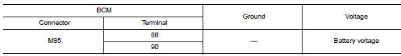
- Check voltage between BCM connector M85 and ground.
Is the inspection result normal? Yes >> go to 3.
No >> repair harness or connector.
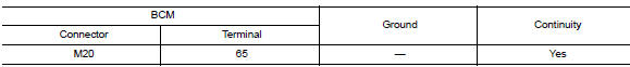
3.Check ground circuit
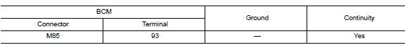
Check continuity between bcm connector m85 and ground.
Is the inspection result normal? YES >> Inspection End.
NO >> Repair harness or connector.
Bcm (body control system) (without intelligent key system)
BCM (BODY CONTROL SYSTEM) (WITHOUT INTELLIGENT KEY SYSTEM) : Diagnosis Procedure
Regarding Wiring Diagram information, refer to BCS-111, "Wiring Diagram".
1.Check fuses and fusible link
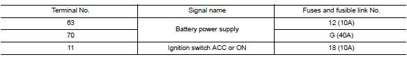
Check that the following fuses and fusible link are not blown.
Is the fuse blown? Yes >> replace the blown fuse or fusible link after repairing the affected circuit.
No >> go to 2.
2.Check power supply circuit
- Turn ignition switch OFF.
- Disconnect bcm connectors.
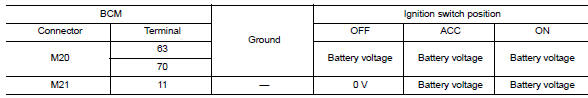
- Check voltage between bcm connector and ground.
Is the inspection result normal? YES >> GO TO 3.
NO >> Repair harness or connector.
Is the inspection result normal? Yes >> go to 3.
No >> repair harness or connector.
3.Check ground circuit
Check continuity between bcm connector and ground.
Is the inspection result normal? YES >> Inspection End.
NO >> Repair harness or connector.

 Battery saver output/power supply circuit
Description
Provides the battery saver output/power supply. Also cuts the power supply
when the interior lamp battery
saver is activated.
Component function check
1.Check battery saver output/po ...
Other materials:
Map lamp
Removal and installation
Removal
Lower front edge of map lamp (1) down from the headlining by
releasing the metal clips, then slide forward to clear pawls at
rear.
: Metal clip
Pawl
Disconnect the harness connectors from the map lamp and remove.
Installation
Installation is in t ...
L terminal circuit (short)
Description
The terminal “l” circuit controls the charge warning lamp. The charge warning
lamp turns on when the ignition
switch is set to on or start. When the generator is providing sufficient voltage
with the engine running,
the charge warning lamp turns off. If the charge warni ...
P1651 Starter motor relay
Description
ECM controls ON/OFF state of the starter relay, according to the engine and
vehicle condition. ECM transmits
a control signal to IPDM E/R by CAN communication.
Under normal conditions, ECM controls and maintains the starter relay in OFF
state during following condition:
Engi ...
