Nissan Sentra Service Manual: P1651 Starter motor relay
Description
ECM controls ON/OFF state of the starter relay, according to the engine and vehicle condition. ECM transmits a control signal to IPDM E/R by CAN communication.
Under normal conditions, ECM controls and maintains the starter relay in OFF state during following condition:
- Engine is running.
- Selector lever is D position. (CVT models)
- Clutch pedal is fully released. (M/T models)
When detecting a decrease in engine speed due to rapid deceleration or heavy load condition, ECM controls and reactivates the starter relay.
IPDM E/R detects a control state of starter relay and starter control relay and transmits a feedback signal to ECM via CAN communication.
DTC Logic
DTC DETECTION LOGIC
NOTE:
- If DTC P1651 is displayed with DTC U1001, perform the trouble diagnosis for DTC U1001. Refer to EC-169, "DTC Logic".
- If DTC P1651 is displayed with DTC P0607, perform the trouble diagnosis for DTC P0607. Refer to EC-350, "DTC Logic".
| DTC No. | CONSULT screen terms (Trouble diagnosis content) | DTC detecting condition | Possible cause |
| P1651 | STR MTR RELAY (Starter motor relay) | A correlated error is detected for 2 seconds or more between a control signal transmitted from ECM and a feedback signal transmitted from IPDM E/R via CAN communication line. |
|
DTC CONFIRMATION PROCEDURE
1.PRECONDITIONING
If DTC Confirmation Procedure has been previously conducted, always perform the following procedure before conducting the next test.
- Turn ignition switch OFF and wait at least 10 seconds.
- Turn ignition switch ON.
- Turn ignition switch OFF and wait at least 10 seconds.
>> GO TO 2.
2.PERFORM DTC CONFIRMATION PROCEDURE FOR MALFUNCTION
- Turn ignition switch OFF and wait at least 10 seconds.
- Start the engine and let it idle at least 30 seconds.
- Check 1st trip DTC.
Is 1st trip DTC detected? YES >> Proceed to EC-402, "Diagnosis Procedure".
NO >> INSPECTION END
Diagnosis Procedure
1.INSPECTION START
Check the starter motor operation.
Is the starter motor operated? YES >> GO TO 3.
NO >> GO TO 2.
2.CHECK DTC WITH IPDM E/R
Check DTC with IPDM E/R. Refer to PCS-10, "CONSULT Function (IPDM E/R)" (with intelligent key), or PCS- 38, "CONSULT Function (IPDM E/R)" (without intelligent key).
Is the inspection result normal? YES >> GO TO 3.
NO >> Perform trouble diagnosis for DTC indicated. Refer to PCS-20, "DTC Index" (with intelligent key), or PCS-48, "DTC Index" (without intelligent key).
3.CHECK CRANKING REQUEST SIGNAL CIRCUIT-1
- Turn ignition switch OFF.
- Disconnect ECM harness connector.
- Disconnect IPDM E/R harness connector.
- Check the continuity between ECM harness connector and IPDM E/R harness connector.
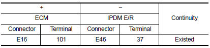
- Also check harness for short to ground to power.
Is the inspection result normal? YES >> GO TO 4.
NO >> Repair or replace error-detected parts.
4.CHECK INTERMITTENT INCIDENT
Check intermittent incident. Refer to GI-39, "Intermittent Incident".
Is the inspection result normal? YES >> Replace IPDM E/R. Refer to PCS-30, "Removal and Installation".
NO >> Repair or replace error-detected parts.
 P1650 Starter motor relay 2
Description
ECM controls ON/OFF state of the starter relay, according to the engine and
vehicle condition. ECM transmits
a control signal to IPDM E/R via BCM by CAN communication.
Under normal ...
 P1652 Starter motor system comm
Description
ECM controls ON/OFF state of the starter relay, according to the engine and
vehicle condition. ECM transmits
a control signal to IPDM E/R via BCM by CAN communication.
Under normal ...
Other materials:
Precaution for Supplemental Restraint System (SRS) "AIR BAG" and "SEAT BELT
PRE-TENSIONER"
The Supplemental Restraint System such as “AIR BAG” and “SEAT BELT PRE-TENSIONER”,
used along
with a front seat belt, helps to reduce the risk or severity of injury to the
driver and front passenger for certain
types of collision. Information necessary to service the system ...
Fuel (Regular Unleaded Gasoline Recommended)
Use unleaded regular gasoline with an octane rating of at least 87 AKI
(Anti-Knock Index) number (Research
octane number 91). E-85 fuel (85% fuel ethanol, 15% unleaded gasoline) may only
be used in vehicles specifically
designed for E-85 fuel (i.e. Flexible Fuel Vehicle - FFV models).
CAUTION ...
Precautions
Precaution for supplemental restraint system (srs) "air bag" and "seat belt
pre-tensioner"
The supplemental restraint system such as “air bag” and “seat belt pre-tensioner”,
used along
with a front seat belt, helps to reduce the risk or severity of injur ...
