
Nissan Sentra Service Manual: Battery saver output/power supply circuit
Description
Provides the battery saver output/power supply. Also cuts the power supply when the interior lamp battery saver is activated.
Component function check
1.Check battery saver output/power supply function
 Consult
- Turn ignition switch on.
- Turn each interior lamp to the ON position.
- Interior room lamp
- Vanity mirror lamps
- Map lamp
- Trunk room lamp
- Select battery saver of bcm (battery saver) active test item.
- While operating the test item, check that each interior room lamp turns ON/OFF.
Off : interior room lamp off
On : interior room lamp on
Is the inspection result normal? Yes >> battery saver output/power supply circuit is normal.
No >> refer to inl-43, "diagnosis procedure".
Diagnosis procedure
Regarding wiring diagram information, refer to inl-17, "wiring diagram".
1.Check battery saver output/power supply output
 Consult
- Turn ignition switch on.
- Select battery saver of bcm (battery saver) active test item.
- While operating the test item, check voltage between BCM connector and ground.
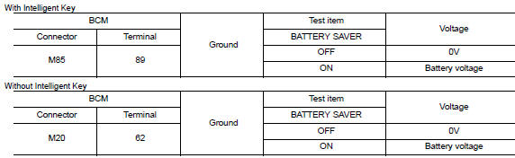
Is the inspection result normal? Yes >> go to 2.
No >> replace bcm after making sure battery saver output/power supply circuit is not shorted to voltage.
Refer to bcs-73, "removal and installation" (with intelligent key) or bcs-126, "removal and installation" (without intelligent key).
2.Check battery saver output/power supply open circuit
- Turn ignition switch off.
- Disconnect the following connectors.
- Bcm
- Interior room lamp
- Vanity mirror lamp LH
- Vanity mirror lamp RH
- Map lamp
- Trunk room lamp
- Check continuity between bcm connector and each interior lamp connector.
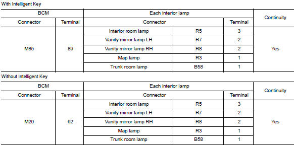
Is the inspection result normal? Yes >> go to 3.
No >> repair or replace the harness or connector.
3.Check battery saver output/power supply short circuit
Check continuity between BCM connector and ground.

Is the inspection result normal? YES >> Check that each interior room lamp has no internal short circuit.
NO >> Repair or replace the harness or connector.
 Power supply and ground circuit
Bcm (body control system) (with intelligent key system)
BCM (BODY CONTROL SYSTEM) (WITH INTELLIGENT KEY SYSTEM) : Diagnosis Procedure
Regarding Wiring Diagram information, refer to BCS-51, "Wir ...
 Interior room lamp control circuit
Description
Controls each interior room lamp (ground side) by pwm signal.
Note:
Pwm signal control period is approximately 250 hz (in the gradual
brightening/dimming).
Component function check
...
Other materials:
Refrigerant pressure sensor
Component Function Check
1.CHECK REFRIGERANT PRESSURE SENSOR OVERALL FUNCTION
Start engine and warm it up to normal operating temperature.
Turn A/C switch and blower fan switch ON.
Check the voltage between ECM harness connector terminals.
Is the inspection result normal?
YES >> ...
Parking lamp circuit
Description
The ipdm e/r (intelligent power distribution module engine room) controls the
tail lamp relay based on inputs
from the bcm over the can communication lines. When the tail lamp relay is
energized, power flows through
fuse 36, located in the ipdm e/r. Power then flows to the front ...
L terminal circuit (open)
Description
The “L” terminal circuit controls the charge warning lamp. The charge warning
lamp turns ON when the ignition
switch is set to ON or START. When the generator is providing sufficient voltage
with the engine running,
the charge warning lamp turns OFF. If the charge warnin ...
