Nissan Sentra Service Manual: Interior room lamp control circuit
Description
Controls each interior room lamp (ground side) by pwm signal.
Note:
Pwm signal control period is approximately 250 hz (in the gradual brightening/dimming).
Component function check
Caution:
Before performing the diagnosis, check that the following are normal.
- Interior room lamp power supply
- Room lamp bulb
- Map lamp bulb
1.Check interior room lamp control function
 Consult active test
- Se the map lamp switch or room lamp switch to door.
- Turn ignition switch on.
- Select int lamp of bcm (int lamp) active test item.
- While operating the test items, check that each interior room lamp turns ON/OFF (gradual brightening/ dimming).
On : interior room lamp gradual brightening
Off : interior room lamp gradual dimming
Does the interior room lamp turns ON/OFF (gradual brightening/dimming)? YES >> Interior room lamp control circuit is normal.
NO >> Refer to INL-45, "Diagnosis Procedure".
Diagnosis procedure
Regarding Wiring Diagram information, refer to INL-17, "Wiring Diagram".
1.Check interior room lamp control output
 Consult active test
- Turn ignition switch OFF
- Remove all the bulbs of room lamp and map lamp.
- Turn ignition switch on.
- Select int lamp of bcm (int lamp) active test item.
- While operating the test item, check continuity between BCM harness connector and ground.
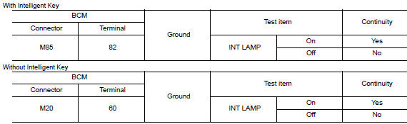
Is the inspection result normal? Yes >> interior room lamp control circuit is operating normally.
Fixed on>>go to 3.
Fixed off>>go to 2.
2.Check interior room lamp control open circuit
- Turn ignition switch off.
- Disconnect bcm connector and room lamp and map lamp connector.
- Check continuity between BCM harness connector and room lamp harness connector.
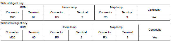
Is the inspection result normal? Yes >> check interior room lamps for an open. If ng, replace lamp in question. Refer to inl-55, "removal and installation" (room lamp) or inl-52, "removal and installation" (map lamp). If ok, replace bcm. Refer to bcs-73, "removal and installation" (with intelligent key), bcs-126, "removal and installation" (without intelligent key).
No >> repair or replace harness or connector.
3.Check interior room lamp control short to ground
- Turn ignition switch off.
- Disconnect BCM connector.
- Check continuity between BCM harness connector and ground.
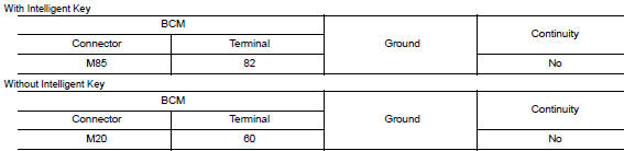
Is the inspection result normal? Yes >> check interior room lamps for an internal short to ground. If ng, replace lamp in question. Refer to inl-55, "removal and installation" (room lamp) or inl-52, "removal and installation" (map lamp). If ok, replace bcm. Refer to bcs-73, "removal and installation" (with intelligent key), bcs-126, "removal and installation" (without intelligent key).
No >> repair or replace harness or connector.
 Battery saver output/power supply circuit
Description
Provides the battery saver output/power supply. Also cuts the power supply
when the interior lamp battery
saver is activated.
Component function check
1.Check battery saver output/po ...
 Trunk room lamp circuit
Description
Controls the trunk room lamp (ground side) to turn the trunk room lamp on and
off.
Diagnosis Procedure
Regarding wiring diagram information, refer to inl-17, "wiring diagram" ...
Other materials:
Instrument panel
Headlight/fog light (if so equipped)/turn
signal switch
Steering wheel switch for trip
computer, audio control and
Bluetooth® Hands-Free Phone System
(if so equipped)
Driver’s supplemental air bag/Horn
Meters and gauges
Cruise control main/set switches
(if so equipped)
...
Main line between ipdm-e and dlc circuit
Diagnosis procedure
1.Check connector
Turn the ignition switch OFF.
Disconnect the battery cable from the negative terminal.
Check the following terminals and connectors for damage, bend and loose
connection (connector side
and harness side).
Harness connector E4
Harness connec ...
Warning signals
To help prevent the vehicle from moving unexpectedly
by erroneous operation of the Intelligent
Key or to help prevent the vehicle from being
stolen, a chime or buzzer sounds from inside and
outside the vehicle and a warning light comes on
in the instrument panel.
When a chime or beep sounds ...
