Nissan Sentra Service Manual: Trunk room lamp circuit
Description
Controls the trunk room lamp (ground side) to turn the trunk room lamp on and off.
Diagnosis Procedure
Regarding wiring diagram information, refer to inl-17, "wiring diagram".
Caution:
Before performing the diagnosis, check that the following are normal.
- Interior room lamp power supply
- Trunk room lamp bulb
1.Check trunk room lamp output
- Turn ignition switch OFF.
- Remove the trunk room lamp bulb.
- Check continuity between bcm harness connector and ground.
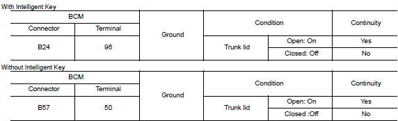
Is the inspection result normal? Yes >> trunk room lamp control circuit is operating normally.
Fixed on>>go to 3.
Fixed off>>go to 2.
2.Check trunk room lamp open circuit
Check continuity between bcm harness connector and trunk room lamp harness connector.
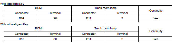
Is the inspection result normal? Yes >> check trunk room lamp for an open. If ng, replace lamp. Refer to inl-56, "removal and installation".
If ok, replace bcm. Refer to bcs-73, "removal and installation" (with intelligent key), bcs-126, "removal and installation" (without intelligent key).
No >> repair or replace harness or connector.
3.Check trunk room lamp short to ground
- Disconnect bcm harness connector.
- Check continuity between BCM harness connector and ground.
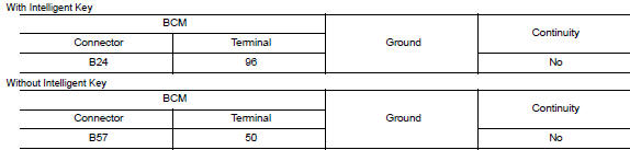
Is the inspection result normal? Yes >> check trunk room lamp for an internal short to ground. If ng, replace lamp. Refer to inl-56, "removal and installation". If ok, replace bcm. Refer to bcs-73, "removal and installation" (with intelligent key), bcs-126, "removal and installation" (without intelligent key).
No >> repair or replace harness or connector.
 Interior room lamp control circuit
Description
Controls each interior room lamp (ground side) by pwm signal.
Note:
Pwm signal control period is approximately 250 hz (in the gradual
brightening/dimming).
Component function check
...
 Push-button ignition switch illumination circuit
Description
Provides the power supply and the ground to control the push-button ignition
switch illumination.
Component function check
1.Check push-button ignition switch illumination operation ...
Other materials:
The oil pressure warning lamp does not turn on
Description
The oil pressure warning lamp stays off when the ignition switch is turned
on.
Diagnosis procedure
1.Check combination meter oil pressure warning light
Select METER/M&A on CONSULT.
Observe oil w/l data monitor while operating the ignition switch.
Is the inspection r ...
General Precaution
WARNING:
When replacing fuel line parts, be sure to observe the following.
Put a “CAUTION: FLAMMABLE” sign in the work area.
Be sure to work in a well ventilated area and have a CO2 fire
extinguisher.
Do not smoke while working on the fuel system. Keep open flames
and sparks ...
Precaution
Precaution for supplemental restraint system (SRS) "air bag" and "seat
belt pre-tensioner"
The supplemental restraint system such as “air bag” and “seat belt pre-tensioner”,
used along
with a front seat belt, helps to reduce the risk or severity of injur ...
