
Nissan Sentra Service Manual: Fuel injector
Component Function Check
1.INSPECTION START
Turn ignition switch to START.
Is any cylinder ignited? YES >> GO TO 2.
NO >> Proceed to EC-450, "Diagnosis Procedure".
2.CHECK FUEL INJECTOR FUNCTION
 With CONSULT
- Start engine.
- Perform “POWER BALANCE” in “ACTIVE TEST” mode of “ENGINE” using CONSULT.
- Check that each circuit produces a momentary engine speed drop
 Without CONSULT
- Let engine idle.
- Listen to each fuel injector operating sound.
Clicking noise should be heard.
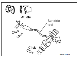
Is the inspection result normal? YES >> INSPECTION END
NO >> Proceed to EC-450, "Diagnosis Procedure".
Diagnosis Procedure
1.CHECK FUSE
- Turn ignition switch OFF.
- Pull out #52 fuse and check that the fuse is not fusing.
Is the inspection result normal? YES >> GO TO 2.
NO >> Replace the fuse after repairing the applicable circuit.
2.CHECK FUEL INJECTOR POWER SUPPLY
- Insert the fuse which pulled out.
- Disconnect fuel injector harness connector.
- Turn ignition switch ON.
- Check the voltage between fuel injector harness connector and ground.
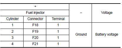
Is the inspection result normal? YES >> GO TO 4.
NO >> GO TO 3.
3.CHECK FUEL INJECTOR POWER SUPPLY CIRCUIT
- Turn ignition switch OFF.
- Disconnect IPDM E/R harness connector.
- Check the continuity between fuel injector harness connector and IPDM E/R harness connector
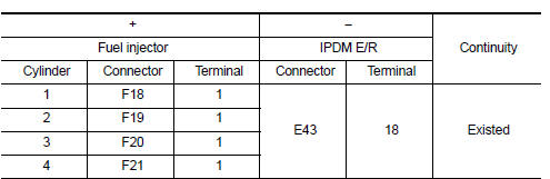
- Also check harness for short to ground.
Is the inspection result normal? YES >> Check intermittent incident. Refer to GI-39, "Intermittent Incident".
NO >> Repair or replace error-detected parts.
4.CHECK FUEL INJECTOR CONTROL CIRCUIT
- Turn ignition switch OFF.
- Disconnect ECM harness connector.
- Check the continuity between fuel injector harness connector and ECM harness connector.
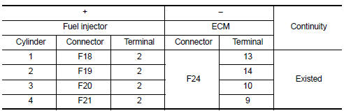
- Also check harness for short to ground and to power.
Is the inspection result normal? YES >> GO TO 5.
NO >> Repair or replace error-detected parts
5.CHECK FUEL INJECTOR
Check the fuel injector. Refer to EC-451, "Component Inspection (Fuel Injector)".
Is the inspection result normal? YES >> Check intermittent incident. Refer to GI-39, "Intermittent Incident" NO >> Replace malfunctioning fuel injector. Refer to EM-40, "Removal and Installation".
Component Inspection (Fuel Injector)
1.CHECK FUEL INJECTOR
- Turn ignition switch OFF.
- Disconnect fuel injector harness connector.
- Check resistance between fuel injector terminals as per the following.

Is the inspection result normal? YES >> INSPECTION END
NO >> Replace malfunctioning fuel injector. Refer to EM-40, "Removal and Installation"
 ASCD Indicator
Component Function Check
1.CHECK ASCD INDICATOR FUNCTION
Check ASCD indicator under the following conditions.
ASCD INDICATOR
CONDITION
SPECIFICATION
CRUISE LAMP
Ig ...
 Fuel pump
Component Function Check
1.CHECK FUEL PUMP FUNCTION
Turn ignition switch ON.
Pinch fuel feed hose with
two fingers.
Fuel pressure pulsation should be felt on the fuel feed
hose for ...
Other materials:
Rear window glass
Exploded View
Rear window glass
Spacer
Rubber dam
Body side outer
Headlining
Roof panel
Trunk lid
Adhesive
12 mm (0.5 in)
7 mm (0.3 in)
2.0 mm (0.08 in)
3 mm (0.1 in)
Removal and Installation
REMOVAL
Partially remove the rear of the headlining (rear edge). R ...
Cooling fan control
SYSTEM DIAGRAM
SYSTEM DESCRIPTION
ECM controls cooling fan speed corresponding to vehicle speed, engine coolant
temperature, refrigerant pressure,
air conditioner ON signal. Then control system has 3-step control
[HIGH/LOW/OFF].
Cooling Fan Operation
Cooling Fan Relay Operation
Whe ...
Power supply and ground circuit
Av control unit
Av control unit : diagnosis procedure
Regarding Wiring Diagram information, refer to AV-234, "Wiring Diagram".
1.Check fuse
Check that the following fuses are not blown.
Are the fuses blown?
Yes >> replace the blown fuse after repairing the affected circuit.
...
