Nissan Sentra Service Manual: Fuel pump
Component Function Check
1.CHECK FUEL PUMP FUNCTION
- Turn ignition switch ON.
- Pinch fuel feed hose
 with
with
two fingers.
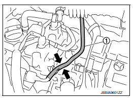
Fuel pressure pulsation should be felt on the fuel feed hose for 1 second after ignition switch is turned ON.
Is the inspection result normal? YES >> INSPECTION END
NO >> Proceed to EC-453, "Diagnosis Procedure".
Diagnosis Procedure
1.CHECK FUEL PUMP POWER SUPPLY CIRCUIT-1
- Turn ignition switch OFF.
- Disconnect ECM harness connector.
- Turn ignition switch ON.
- Check the voltage between ECM harness connector and ground.

Is the inspection result normal? YES >> GO TO 3.
NO >> GO TO 2.
2.CHECK FUEL PUMP POWER SUPPLY CIRCUIT-2
- Turn ignition switch OFF.
- Disconnect IPDM E/R harness connector.
- Check the continuity between IPDM E/R harness connector and ECM harness connector.
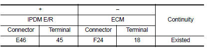
- Also check harness for short to ground and short to power.
Is the inspection result normal? YES >> GO TO 8.
NO >> Repair or replace error-detected parts.
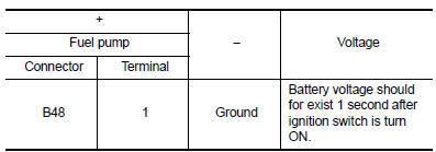
3.CHECK FUEL PUMP POWER SUPPLY CIRCUIT-3
- Turn ignition switch OFF.
- Reconnect all harness connectors disconnected.
- Disconnect fuel pump harness connector.
- Turn ignition switch ON.
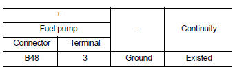
- Check the voltage between fuel pump harness connector and ground.
Is the inspection result normal? YES >> GO TO 6.
NO >> GO TO 4.
4.CHECK FUSE
- Turn ignition switch OFF.
- Disconnect 15A fuse (No. 50) from IPDM E/R.
- Check 15A fuse.
Is the inspection result normal? YES >> GO TO 5.
NO >> Replace 15A fuse.
5.CHECK FUEL PUMP POWER SUPPLY CIRCUIT-4
- Turn ignition switch OFF.
- Disconnect IPDM E/R harness connector
- Check the continuity between IPDM E/R harness connector and fuel pump harness connector.
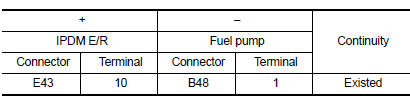
- Also check harness for short to ground and short to power.
Is the inspection result normal? YES >> GO TO 6.
NO >> Repair or replace error-detected parts.
6.CHECK FUEL PUMP GROUND CIRCUIT
- Turn ignition switch OFF.
- Check the continuity between fuel pump harness connector and ground.
- Also check harness for short to power.
Is the inspection result normal? YES >> GO TO 7.
NO >> Repair or replace error-detected parts.
7.CHECK FUEL PUMP
Check fuel pump. Refer to EC-455, "Component Inspection (Fuel Pump)".
Is the inspection result normal? YES >> GO TO 8.
NO >> Replace fuel filter and fuel pump. Refer to FL-6, "Exploded View".
8.CHECK INTERMITTENT INCIDENT
Check intermittent incident. Refer to GI-39, "Intermittent Incident".
Is the inspection result normal? YES >> Replace IPDM E/R. Refer to PCS-30, "Removal and Installation" (With intelligent key) or PCS-58, "Removal and Installation" (Without intelligent key).
NO >> Repair or replace error-detected parts.
Component Inspection (Fuel Pump)
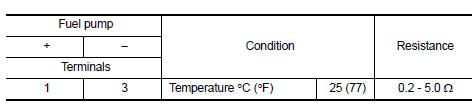
1.CHECK FUEL PUMP
- Turn ignition switch OFF
- Disconnect fuel level sensor unit and fuel pump harness connector.
- Check resistance between fuel pump terminals as follows.
Is the inspection result normal? YES >> INSPECTION END
NO >> Replace fuel filter and fuel pump. Refer to FL-6, "Removal and Installation".
 Fuel injector
Component Function Check
1.INSPECTION START
Turn ignition switch to START.
Is any cylinder ignited?
YES >> GO TO 2.
NO >> Proceed to EC-450, "Diagnosis Procedure".
2.CH ...
 Ignition signal
Component Function Check
1.INSPECTION START
Turn ignition switch OFF.
Start engine.
Does the engine start?
YES >> GO TO 2.
NO >> Proceed to EC-456, "Diagnosis Procedure& ...
Other materials:
Cooling fan control
SYSTEM DIAGRAM
SYSTEM DESCRIPTION
ECM controls cooling fan speed corresponding to vehicle speed, engine coolant
temperature, refrigerant pressure,
air conditioner ON signal. Then control system has 3-step control
[HIGH/LOW/OFF].
Cooling Fan Operation
Cooling Fan Relay Operation
Whe ...
B1429 Seat belt buckle switch RH
Description
DTC B1429 SEAT BELT BUCKLE SWITCH RH
The air bag diagnosis sensor unit monitors the seat belt buckle switch RH
status. If the control unit detects an
open or short condition in the circuit, it will set the DTC.
PART LOCATION
Refer to SRC-5, "Component Parts Location".
D ...
Telescopic operation
Pull the lock lever down 1 and adjust the steering
wheel forward or backward 3 to the desired
position.
Push the lock lever up 1 firmly to lock the
steering wheel in place.
WARNINGDo not adjust the steering wheel any
closer to you than is necessary for proper
steering operation a ...
