Nissan Sentra Service Manual: Ecu diagnosis information
BCM
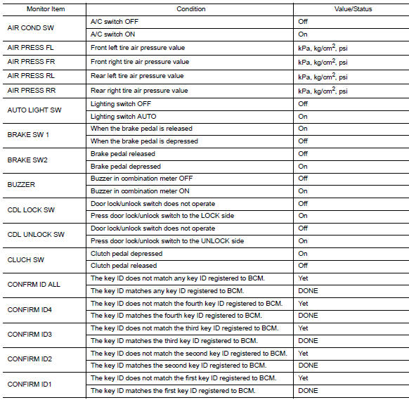
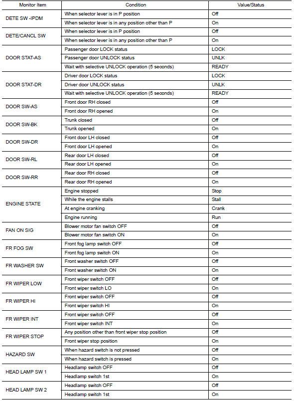
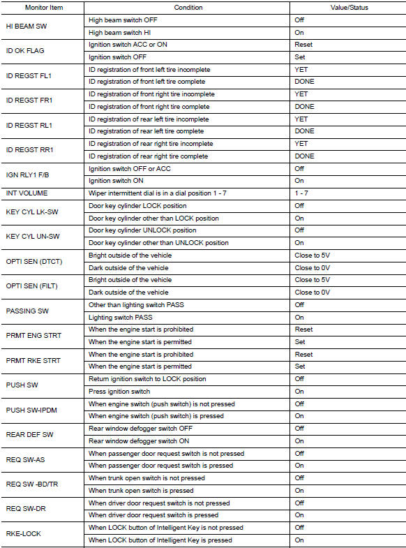
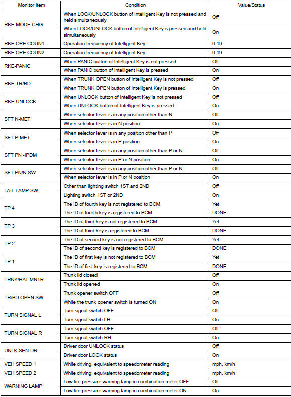
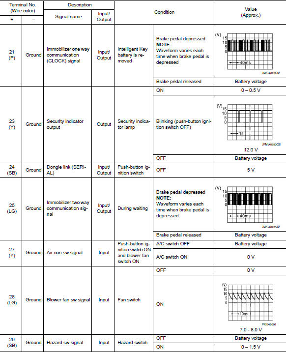
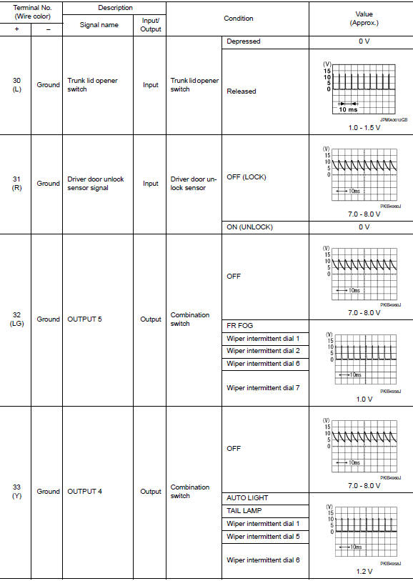
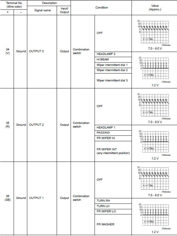
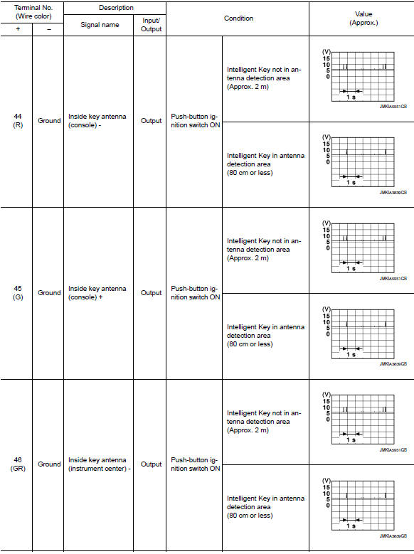
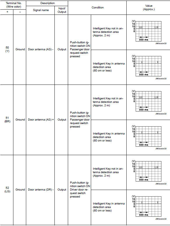
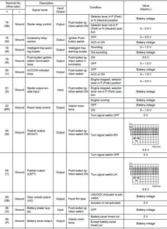
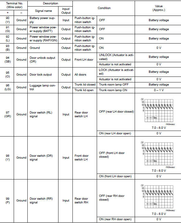
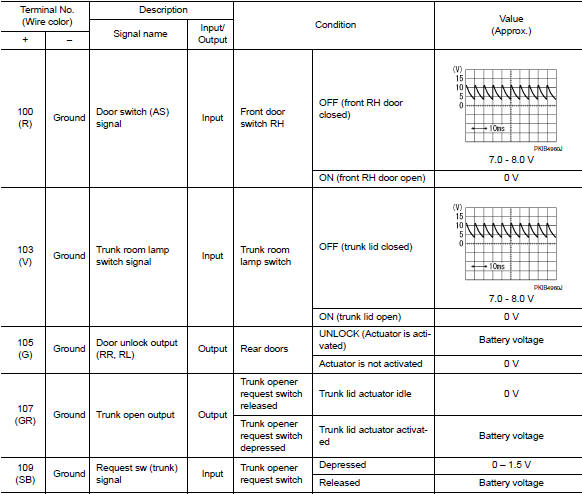
Reference value
Note:
The signal tech ii tool (j-50190) can be used to perform the following functions. Refer to the signal tech ii user guide for additional information.
- Activate and display tpms transmitter ids
- Display tire pressure reported by the tpms transmitter
- Read TPMS DTCs
- Register TPMS transmitter IDs
- Check intelligent key relative signal strength
- Confirm vehicle intelligent key antenna signal strength
Values on the diagnosis tool
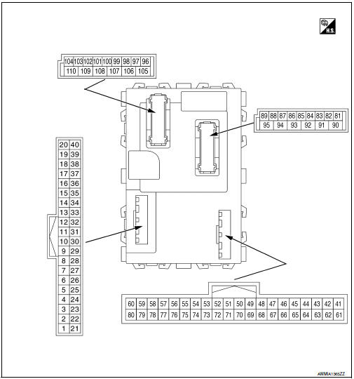
Terminal layout
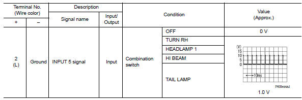
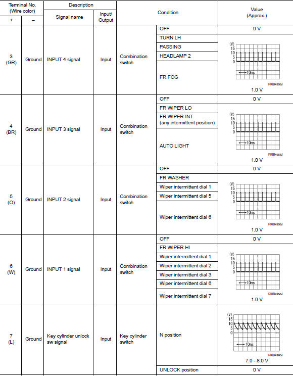
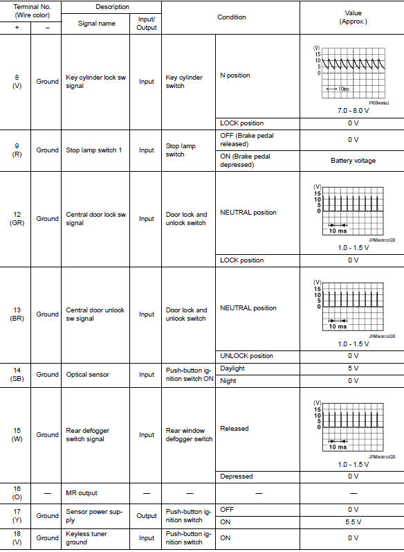
Physical values
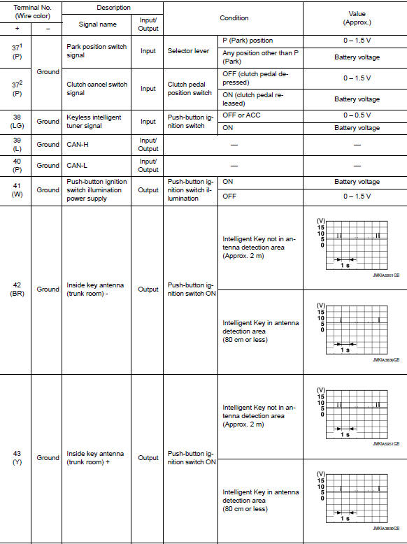

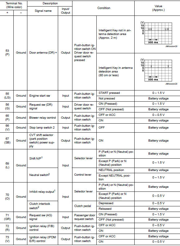
1: With cvt
2: With m/t
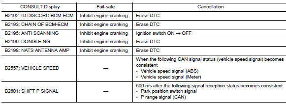
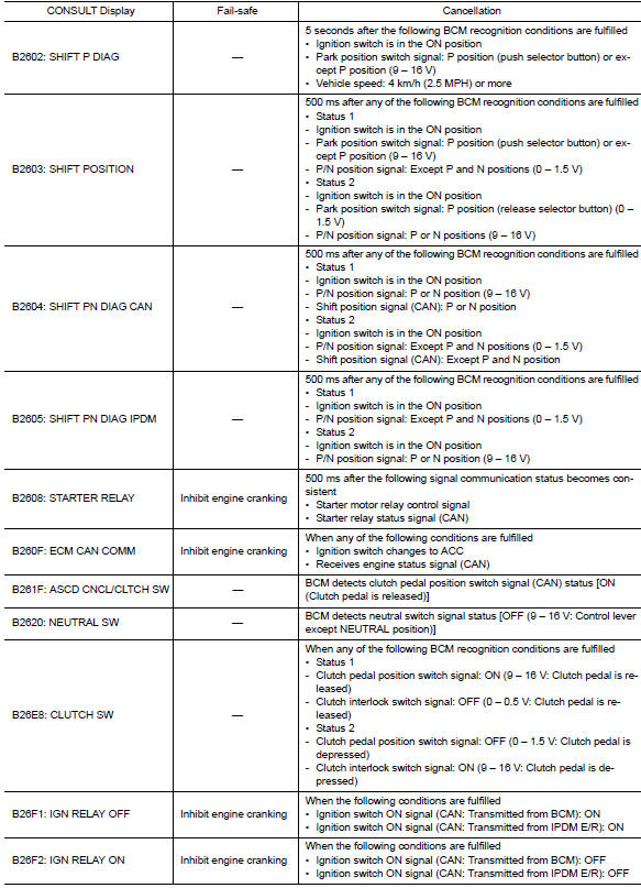
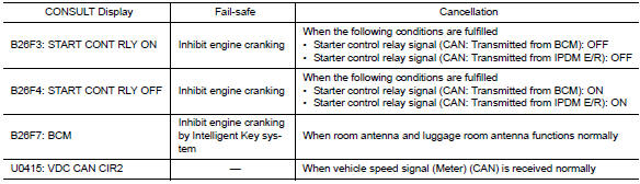
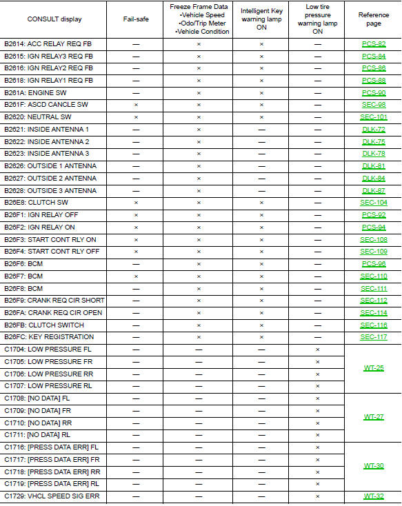
Fail-safe
Bcm performs fail-safe control when the following dtcs are detected.
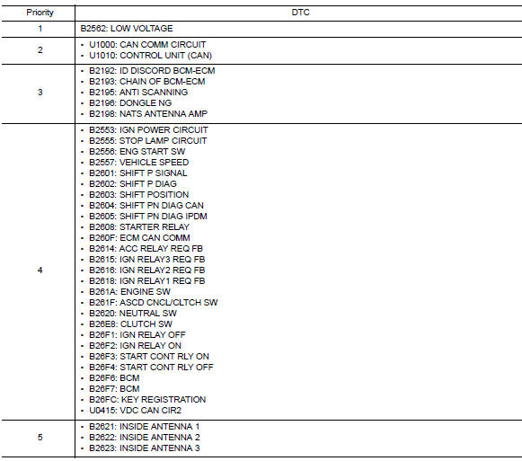
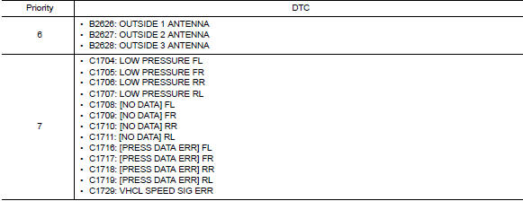
Dtc inspection priority chart
If more than one DTC is displayed at the same time, perform inspections based on the following priority chart.
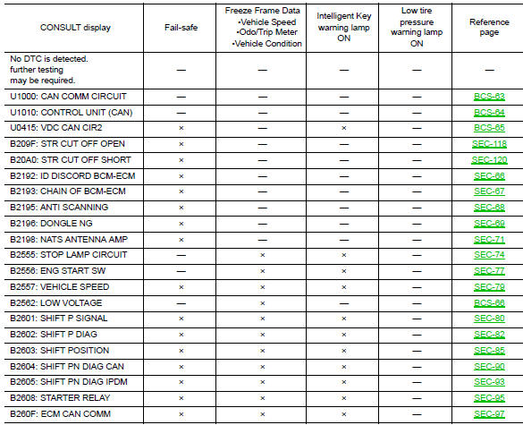
Dtc index
Note:
The details of time display are as follows.
- Crnt: a malfunction is detected now.
- Past: a malfunction was detected in the past.
IGN counter is displayed on Freeze Frame Data.
 Diagnosis system (bcm)
Common item
COMMON ITEM : CONSULT Function (BCM - COMMON ITEM)
Application item
Consult performs the following functions via can communication with bcm.
Direct diagnostic mode
Descriptio ...
 Wiring diagram
BCM
Wiring diagram
...
Other materials:
Basic inspection
Component inspection
Inspection
AFTER A COLLISION
WARNING:
Inspect all seat belt assemblies including retractors and attaching
hardware after any collision.
NISSAN/INFINITI recommends that all seat belt assemblies in use during a
collision be replaced
unless the collision was minor and t ...
Bluetooth® Hands-Free Phone System voice commands
To access the Bluetooth® Hands-Free Phone
System voice commands:
Press the button.
Say “Call” and then a name in the vehicle
phonebook to call that entry. Otherwise, say
“Phone” to access various phone commands.
If the Bluetooth® has been set to “Off”, the
system announ ...
Moonroof switch
Removal and installation
REMOVAL
Remove the map lamp. Refer to INL-52, "Removal and Installation".
Release the pawls and remove the moonroof switch finisher (1).
: Pawl
Release the pawls and remove the moonroof switch (2).
: Pawl
INSTALLATION
Installation is in the ...
