
Nissan Sentra Service Manual: Encoder
Driver side
DRIVER SIDE : Description
Detects condition of the front power window motor lh operation and transmits to main power window and door lock/unlock switch as pulse signal.
DRIVER SIDE : Component Function Check
1. Check encoder operation
Check front door glass lh perform auto open/close operation normally with main power window and door lock/unlock switch.
Is the inspection result normal? Yes >> encoder operation is ok.
No >> refer to pwc-50, "driver side : diagnosis procedure".
DRIVER SIDE : Diagnosis Procedure
Regarding wiring diagram information, refer to pwc-18, "wiring diagram".
Encoder circuit check
1. Check encoder operation
- Connect front power window motor lh.
- Turn ignition switch ON.
- Check signal between main power window and door lock/unlock switch connector d5 and ground with oscilloscope.
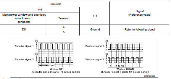
Is the inspection result normal? YES >> Check intermittent incident. Refer to GI-39, "Intermittent Incident".
NO >> GO TO 2.
2. Check front power window motor lh power supply
- Turn ignition switch on.
- Check voltage between front power window motor lh connector d8 and ground.

Is the inspection result normal? YES >> GO TO 4.
NO >> GO TO 3.
3. Check harness continuity 1
- Turn ignition switch OFF.
- Disconnect main power window and door lock/unlock switch and front power window motor lh.
- Check continuity between main power window and door lock/unlock switch connector D5 and front power window motor connector D8.

- Check continuity between main power window and door lock/unlock switch connector d5 and ground.

Is the inspection result normal? YES >> Replace main power window and door lock/unlock switch. Refer to PWC-70, "Removal and Installation".
After that, refer to PWC-29, "Work Procedure".
NO >> Repair or replace harness or connectors.
4. Check ground circuit
- Turn ignition switch off.
- Disconnect front power window motor LH.
- Check continuity between front power window motor lh connector d8 and ground.

Is the inspection result normal? Yes >> go to 6.
No >> go to 5.
5. Check harness continuity 2
- Disconnect main power window and door lock/unlock switch.
- Check continuity between main power window and door lock/unlock switch connector d5 and front power window motor lh connector d8.

Is the inspection result normal? YES >> Check main power window and door lock/unlock switch. Refer to PWC-36, "POWER WINDOW MAIN SWITCH : Component Inspection".
NO >> Repair or replace the harness or connectors.
6. Check harness continuity 3
- Disconnect main power window and door lock/unlock switch.
- Check continuity between main power window d5 and door lock/unlock switch connector and front power window motor lh connector d8.

- Check continuity between main power window and door lock/unlock switch connector d5 and ground.

Is the inspection result normal? Yes >> replace front power window motor lh. Refer to gw-16, "removal and installation". After that, refer to pwc-29, "work procedure".
No >> repair or replace harness or connectors.
DRIVER SIDE : Special Repair Requirement
1. Perform initialization procedure
Perform initialization procedure.
Refer to pwc-29, "work procedure".
Is the inspection result normal? Yes >> inspection end.
No >> check intermittent incident. Refer to gi-39, "intermittent incident".
 Power window motor
DRIVER SIDE
DRIVER SIDE : Description
Door glass moves up/down by receiving the signal from main power window and
door lock/unlock switch
DRIVER SIDE : Component Function Check
1. Check front po ...
 Door switch
With intelligent key
WITH INTELLIGENT KEY : Component Function Check
1.Check function
Select DOOR LOCK of BCM using CONSULT.
Select DOOR SW-DR, DOOR SW-AS, DOOR SW-RL and DOOR SW-RR in DATA M ...
Other materials:
System description
Component parts
Body control system
BODY CONTROL SYSTEM : Component Parts Location
Bcm (view with instrument panel removed)
Combination switch reading system
COMBINATION SWITCH READING SYSTEM : Component Parts Location
BCM (view with combination meter
removed)
Combination s ...
P2127, P2128 APP Sensor
DTC Logic
DTC DETECTION LOGIC
DTC No.
CONSULT screen terms
(Trouble diagnosis content)
DTC detecting condition
Possible cause
P2127
APP SEN 2/CIRC
(Throttle/Pedal position
sensor/switch “E” circuit
low)
An excessively low voltage from the APP
...
System description
Component parts
Component parts location
Ipdm e/r (contains ignition relay-1)
Bcm (view with instrument panel removed)
Fuse block (j/b) (front)
Fuse block (j/b) (back)
Blower relay
Ignition relay-2
Accessory relay-1
Push-button ignition switch
Component description
...
