Nissan Sentra Service Manual: Dtc/circuit diagnosis
U1000 can comm circuit
Description
Refer to LAN-7, "CAN COMMUNICATION SYSTEM : System Description".
Dtc logic
Dtc detection logic
| Consult display | Dtc detection condition | Possible cause |
| Can comm circuit [u1000] | When ipdm e/r cannot communicate with can communication signal continuously for 2 seconds or more | In can communication system, any item (or items) of
the following listed below is malfunctioning.
|
Diagnosis procedure
1. Perform self diagnostic result
- Turn ignition switch on and wait for 2 second or more.
- Check “self-diag results” of ipdm e/r.
Is “can comm circuit” displayed? Yes >> refer to lan-16, "trouble diagnosis flow chart".
No >> refer to gi-39, "intermittent incident".
B2098 ignition relay on stuck
Dtc logic
Dtc detection logic
| Consult display | Dtc detection condition | Possible cause |
| Ign relay on [b2098] | The ignition relay ON is detected for 1 second at ignition switch OFF (CPU monitors the status at the contact and excitation coil circuits of the ignition relay inside it) | coil circuits of the ignition relay inside it) IPDM E/R |
Dtc confirmation procedure
1.Perform dtc confirmation procedure
- Turn the power supply position to start under the following conditions and wait for at least 1 second.
Cvt model
- Cvt selector lever is in the p (park) or n (neutral) position.
- Depress the brake pedal
M/t model
- Selector lever is in the Neutral position.
- Depress the clutch pedal
- Check “self-diagnostic result” with consult.
Is DTC detected? YES >> Refer to PCS-55, "Diagnosis Procedure".
NO >> Inspection End.
Diagnosis procedure
1. Perform self diagnostic result
Perform self diagnostic result of ipdm e/r using consult.
Is display history of dtc b2098 crnt? Yes >> replace ipdm e/r. Refer to pcs-58, "removal and installation".
No >> refer to gi-39, "intermittent incident".
B2099 ignition relay off stuck
Dtc logic
Dtc detection logic
| Consult display | Dtc detection condition | Possible cause |
| Ign relay off [b2099] | The ignition relay OFF is detected for 1 second at ignition switch ON (CPU monitors the status at the contact and excitation coil circuits of the ignition relay inside it) | IPDM E/R |
Dtc confirmation procedure
1.Perform dtc confirmation procedure
- Turn the power supply position to start under the following conditions and wait for at least 1 second.
Cvt model
- Cvt selector lever is in the p (park) or n (neutral) position.
- Depress the brake pedal
M/t model
- Selector lever is in the neutral position.
- Depress the clutch pedal
- Check “Self-diagnostic result” with CONSULT.
Is DTC detected? YES >> Refer to PCS-56, "Diagnosis Procedure".
NO >> Inspection End.
Diagnosis procedure
1. Perform self diagnostic result
Perform Self Diagnostic Result of IPDM E/R using CONSULT.
Is display history of DTC B2099 CRNT? YES >> Replace IPDM E/R. Refer to PCS-58, "Removal and Installation".
NO >> Refer to GI-39, "Intermittent Incident".
Power supply and ground circuit
Diagnosis procedure
Regarding Wiring Diagram information, refer to PCS-49, "Wiring Diagram".
1. Check fuse and fusible links
Check that the following ipdm e/r fusible links are not blown.
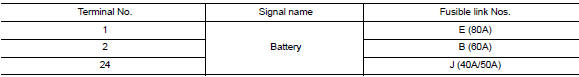
Is the fusible link blown? Yes >> replace the blown fusible link after repairing the affected circuit.
No >> go to 2
2. Check power supply circuit
- Disconnect IPDM E/R connector E42 and E44.
- Check voltage between ipdm e/r connector e42 and e44 and ground.
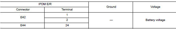
Is the inspection result normal? Yes >> go to 3
NO >> Repair harness or connectors.
3. Check ground circuit
- Turn ignition switch off.
- Disconnect ipdm e/r connector e47 and e48.
- Check continuity between ipdm e/r connector e47 and e48 and ground.
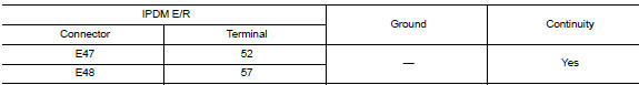
Is the inspection result normal? Yes >> inspection end.
No >> repair harness or connectors.
 Wiring diagram
Ipdm e/r (intelligent power distribution module engine room)
Wiring diagram
...
 Removal and installation
Ipdm e/r
Exploded view
Ipdm e/r
IPDM E/R cover A
Ipdm e/r cover b
Removal and installation
Caution:
Ipdm e/r integrated relays are not serviceable and must not be removed
from unit. ...
Other materials:
Trunk room trim
Exploded View
Trunk floor trim
Trunk front floor spacer (LH)
Trunk side finisher (LH)
Reflector box assembly*
Trunk rear plate
Trunk side finisher (RH)
Trunk front floor spacer (RH)
Clip
Pawl
Trunk rear plate
TRUNK REAR PLATE : Removal and Installation
REMOVAL
Remove ...
6M/T
6M/T : Exploded View (LH)
Circular clip
Dust shield
Slide joint housing
Snap ring
Spider assembly
Boot band
Boot
Shaft
Damper band
Dynamic damper
Circular clip
Joint sub-assembly
Wheel side
6M/T : Disassembly and Assembly (LH)
DISASSEMBLY (WHEEL SIDE)
CAUTION:
...
Inspection and adjustment
Additional service when replacing control unit
ADDITIONAL SERVICE WHEN REPLACING CONTROL UNIT : Description
WARNING:
Always perform zero point reset using CONSULT when removing and
installing the front passenger
seat or servicing the occupant classification system. If zero point reset is not ...
