Nissan Sentra Service Manual: Cooling fan control
SYSTEM DIAGRAM
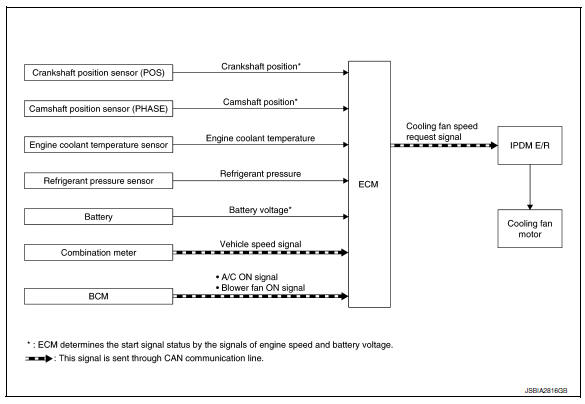
SYSTEM DESCRIPTION
ECM controls cooling fan speed corresponding to vehicle speed, engine coolant temperature, refrigerant pressure, air conditioner ON signal. Then control system has 3-step control [HIGH/LOW/OFF].
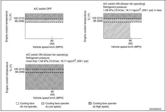
Cooling Fan Operation
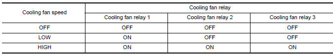
Cooling Fan Relay Operation
When IPDM E/R recieves a cooling fan speed request signal, IPDM E/R controls the cooling fan ralay 1, 2 and 3.
 Air conditioning cut control
AIR CONDITIONING CUT CONTROL : System Description
SYSTEM DIAGRAM
INPUT/OUTPUT SIGNAL CHART
Sensor
Input Signal to ECM
ECM function
Actuator
Crankshaft position sensor ( ...
 Starter motor drive control
STARTER MOTOR DRIVE CONTROL : System Description
SYSTEN DIAGRAM
*1: CVT models
*2: M/T models
INPUT/OUTPUT SIGNAL CHART
Sensor
Input signal to ECM
ECM function
Actuator
...
Other materials:
Diagnosis system (bcm) (with intelligent key system)
Common item
COMMON ITEM : CONSULT Function (BCM - COMMON ITEM)
APPLICATION ITEM
CONSULT performs the following functions via CAN communication with BCM.
Direct Diagnostic Mode
Description
ECU identification
The BCM part number is displayed.
Self Diagnostic Result
...
Air bags, seat belts and child restraints
Top tether anchor
Rear seat belts
Roof-mounted curtain side-impact
supplemental air bag
Head restraints/headrests
Front seat belts
Supplemental front-impact air bags
Front seats
Occupant classification sensor
Seat belt with pretensioner
Front seat-mounted side-impact
sup ...
Diagnosis and repair workflow
Work flow
Overall sequence
Detailed flow
1. Obtain information about symptom
Interview the customer to obtain as much information as possible about the
conditions and environment under
which the malfunction occurred.
>> GO TO 2.
2. Confirm concern
Check the malfunction on the veh ...
