Nissan Sentra Service Manual: Air conditioning cut control
AIR CONDITIONING CUT CONTROL : System Description
SYSTEM DIAGRAM
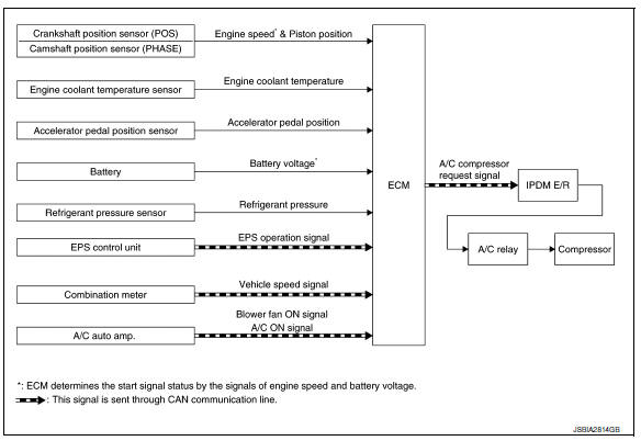
INPUT/OUTPUT SIGNAL CHART
| Sensor | Input Signal to ECM | ECM function | Actuator | |
| Crankshaft position sensor (POS) | Engine speed* Piston position | Air conditioner cut control | IPDM E/R
↓ Air conditioner relay ↓ Compressor |
|
| Camshaft position sensor (PHASE) | ||||
| Engine coolant temperature sensor | Engine coolant temperature | |||
| Accelerator pedal position sensor | Accelerator pedal position | |||
| Battery | Battery voltage* | |||
| Refrigerant pressure sensor | Refrigerant pressure | |||
| EPS control unit | CAN communication | EPS operation signal | ||
| Combination meter | CAN communication | Vehicle speed signal | ||
| A/C auto amp. | CAN communication |
|
||
*: ECM determines the start signal status by the signals of engine speed and battery voltage.
SYSTEM DESCRIPTION
This system improves engine operation when the air conditioner is used.
Under the following conditions, the air conditioner is turned off.
- When the accelerator pedal is fully depressed.
- When cranking the engine.
- At high engine speeds.
- When the engine coolant temperature becomes excessively high.
- When operating power steering during low engine speed or low vehicle speed.
- When engine speed is excessively low.
- When refrigerant pressure is excessively low or high.
 Fuel filler cap warning system
SYSTEM DIAGRAM
SYSTEM DESCRIPTION
The fuel filler cap warning system alerts the driver to the prevention of the
fuel filler being left uncapped and
malfunction occurrences after refueling, by ...
 Cooling fan control
SYSTEM DIAGRAM
SYSTEM DESCRIPTION
ECM controls cooling fan speed corresponding to vehicle speed, engine coolant
temperature, refrigerant pressure,
air conditioner ON signal. Then control syst ...
Other materials:
Connecting procedure
NOTE:
The connecting procedure must be performed
when the vehicle is stationary. If the
vehicle starts moving during the procedure,
the procedure will be cancelled.
To connect a phone to the Bluetooth® Hands-
Free Phone System:
Press the SETTING button.
Use the TUNE/FOLDER knob to s ...
ECU diagnosis information
TCM
Reference Value
CONSULT DATA MONITOR STANDARD VALUE
NOTE:
The following table includes information (items) inapplicable to this
vehicle. For information (items) applicable
to this vehicle, refer to CONSULT display items.
In CONSULT, electric shift timing or lock-up timing, i.e. op ...
Precaution for Supplemental Restraint System (SRS) "AIR BAG" and "SEAT
BELT PRE-TENSIONER"
The Supplemental Restraint System such as “AIR BAG” and “SEAT BELT PRE-TENSIONER”,
used along
with a front seat belt, helps to reduce the risk or severity of injury to the
driver and front passenger for certain
types of collision. Information necessary to service the system ...
