
Nissan Sentra Service Manual: Unit removal and installation
TRANSMISSION ASSEMBLY
Exploded View
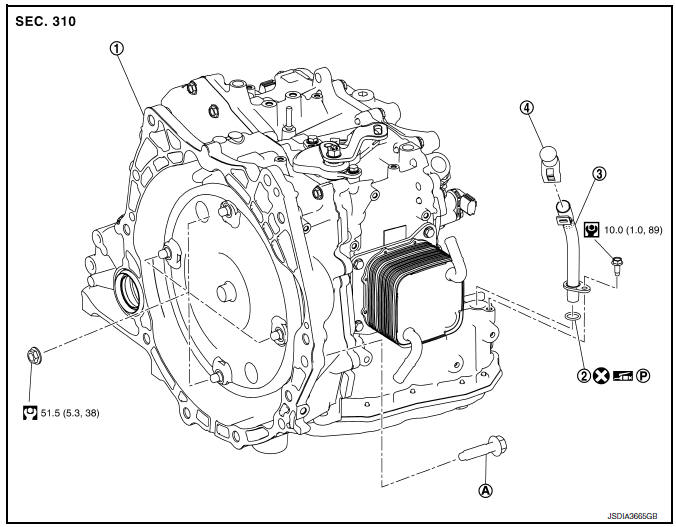
- Transaxle assembly
- O-ring
- CVT fluid charging pipe
- CVT fluid charging pipe cap
- Tightening must be done following the installation procedure. Refer to TM-283, "Removal and Installation".
 : Always replace after every
disassembly.
 : NВ·m (kg-m, ft-lb)
 : NВ·m (kg-m, in-lb)
 : Apply petroleum jelly
Removal and Installation
REMOVAL
WARNING:
Do not remove the radiator cap when the engine is hot. Serious burns could occur from high-pressure coolant escaping from the radiator. Wrap a thick cloth around the cap. Slowly push down and turn it a quarter turn to allow built-up pressure to escape. Carefully remove the cap by pushing it down and turning it all the way.
CAUTION:
- Perform these steps after the coolant temperature has cooled sufficiently.
- Before replacing TCM and transaxle assembly as a set, perform "ADDITIONALSERVICE WHEN REPLACING TCM AND TRANSAXLE ASSEMBLY". Refer to TM-144, "Work Procedure".
NOTE:
- When removing components such as hoses, tubes/line, etc., cap or plug openings to prevent fluid from spilling.
- When replacing the TCM and transaxle assembly as a set, replace the transaxle assembly first and then replace the TCM. Refer to TM-142, "Description".
- Remove the engine and transaxle assembly. Refer to EM-82, "M/T : Removal and Installation" (MT) or EM-86, "CVT : Removal and Installation" (CVT).
- Disconnect the connectors and harnesses.
- For CVT unit harness connector, refer to TM-69, "Removal and Installation Procedure for CVT Unit Connector".
- Transmission position switch harness connector
- Primary pulley speed sensor harness connector
- Secondary pulley speed sensor harness connector
- Output speed sensor harness connector
- Ground
- Rotate the crankshaft and remove the nuts that secure the drive plate to the torque converter from the stator motor mount.
CAUTION:
Rotate crankshaft clockwise (as viewed from the front of the engine).
- Remove the bolts (engine to transaxle) that fasten the transaxle assembly and engine assembly.
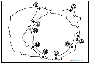
| Bolt position | (A) | (B) |
| Direction of insertion | Transaxle to engine | Engine to transaxle |
| Quantity | 2 | 6 |
- Remove transmission bracket.
- Lift the transaxle from the front suspension member.
INSTALLATION
Installation is in the reverse order of removal.
CAUTION:
- When replacing an engine or transaxle you must make sure any dowels are installed correctly during re-assembly
- Improper alignment caused by missing dowels may cause vibration, oil leaks or breakage of drive train components.
- Do not reuse O-rings or copper sealing washers.
- When turning crankshaft, turn it clockwise as viewed from the front of the engine
- When tightening the nuts for the torque converter while securing the crankshaft pulley bolt, be sure to confirm the tightening torque of the crankshaft pulley bolt. Refer to EM-49, "Removal and Installation".
- After converter is installed to drive plate, rotate crankshaft several turns to check that CVT rotates freely without binding.
- When installing the CVT to the engine, align the matching mark on the drive plate with the matching mark on the torque converter
NOTE:
Install the transaxle assembly and engine assembly mounting bolts according to the following standards.
| Bolt position | (A) | (B) |
| Direction of insertio | Transaxle to engine | Engine to transaxle |
| Quantity | 2 | 6 |
| Nominal length [mm (in)] | 50 (1.97) | |
| Tightening torque NВ·m (kg-m, ft-lb) | 62 (6.3, 46) | |
Inspection and Adjustment
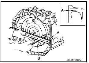
INSPECTION BEFORE INSTALLATION
Check the dimension (A) between the converter housing and torque converter.
B : Scale
C : Straightedge
Dimension (A) : TM-289, "Torque Converter"
INSPECTION AFTER INSTALLATION
Check the following items:
- CVT fluid leakage. Refer to TM-250, "Inspection"
- For CVT position, refer to TM-150, "Inspection".
- Start the engine and check for coolant leakage from the parts which are removed and reinstalled.
ADJUSTMENT AFTER INSTALLATION
- Adjust the CVT fluid level. TM-251, "Adjustment".
- Perform “ADDITIONAL SERVICE WHEN REPLACE TRANSAXLE ASSEMBLY”. Refer to TM-144, "Description".
 Electric oil pump
Exploded View
Transaxle assembly
Electric oil pump sub harness
O-ring
Electric oil pump and motor assembly
CVT fluid
Removal and Installation
REMOVAL
Remove neighboring parts ...
 Unit disassembly and assembly
TORQUE CONVERTER AND CONVERTER HOUSING OIL SEAL
Exploded View
Transaxle assembly
Torque converter
Converter housing oil seal
: Apply CVT Fluid
Disassembly
Remove transaxle ass ...
Other materials:
Removal and installation
BCM
Removal and installation
Note:
Before replacing BCM, perform “READ CONFIGURATION” to save or print
current vehicle specification. Refer
to BCS-61, "CONFIGURATION (BCM) : Description".
Removal
Disconnect the negative battery terminal. Refer to pg-52, "removal a ...
Engine assembly M/T
M/T : Exploded View
Washer
Upper torque rod (RH)
Engine mounting insulator (RH)
Rear torque rod bracket
Rear torque rod
Engine mounting bracket (LH)
Engine mounting frame support (LH)
Engine mounting insulator (LH)
CAUTION:
Check that the stud bolt (*2) is tight at the spe ...
Dtc/circuit diagnosis
Eco mode switch
Component function check
1. Check eco mode switch operation
Turn ignition switch ON.
Check ECO mode indicator lamp turns ON/OFF on combination meter when
turn ECO mode switch ON/
OFF.
Is the inspection result normal?
Yes >> inspection end
No >> go to dm ...
