
Nissan Sentra Service Manual: System description
DESCRIPTION
Engine Cooling System Schematic
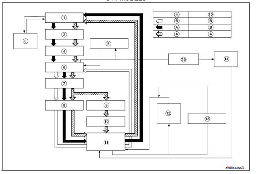
CVT Models
- Radiator
- Water inlet
- Reservoir tank
- Thermostat
- Engine oil cooler
- Thermostat housing
- Water pump
- Cylinder head
- Cylinder block
- Water control valve
- Water outlet
- Heater
- Electric throttle control actuator
- CVT oil warmer
- Heater thermostat
- Open
- Closed
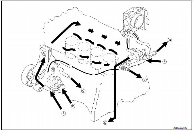
CVT models
- From heater thermostat
- From radiator
- To engine oil cooler
- To engine oil cooler
- To CVT oil warmer
- From heater core
- To heater core
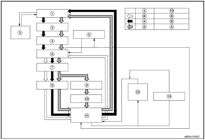
M/T Models
- Radiator
- Water inlet
- Reservoir tank
- Thermostat
- Engine oil cooler
- Thermostat housing
- Water pump
- Cylinder head
- Cylinder block
- Water control valve
- Water outlet
- Heater
- Electric throttle control actuator
- Open
- Closed
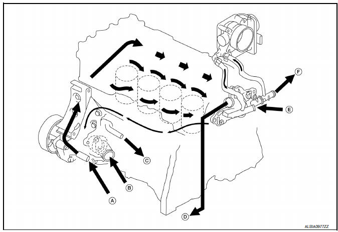
- From heater thermostat
- From radiator
- To engine oil cooler
- To filler neck
- From heater core
- To heater core
 Preparation
Special Service Tool
The actual shape of the tools may differ from those illustrated here.
Commercial Service Tool
...
 Symptom diagnosis
OVERHEATING CAUSE ANALYSIS
Troubleshooting Chart
Symptom
Check items
Cooling system
parts
malfunction
Poor heat transfer
Water pump malfunction
Worn or lo ...
Other materials:
U1000 CAN Comm circuit
Description
Can (controller area network) is a serial communication line for
real time application. It is an on-vehicle multiplex
communication line with high data communication speed and excellent error
detection ability. Many electronic
control units are equipped onto a vehicle, and each co ...
Normal operating condition
Description
FUEL CUT CONTROL (AT NO LOAD AND HIGH ENGINE SPEED)
If the engine speed is above 2,500 rpm under no load (for example, the
selector lever position is neutral and
engine speed is over 2,500 rpm) fuel will be cut off after some time. The exact
time when the fuel is cut off varies
b ...
P0138 HO2S2
DTC Logic
DTC DETECTION LOGIC
The heated oxygen sensor 2 has a much longer switching time between rich and
lean than the air fuel ratio (A/
F) sensor 1. The oxygen storage capacity of the three way catalyst (manifold)
causes the longer switching
time.
MALFUNCTION A
To judge the malfunction ...
