Nissan Sentra Service Manual: Removal and installation
ACCELERATOR CONTROL SYSTEM
Exploded View
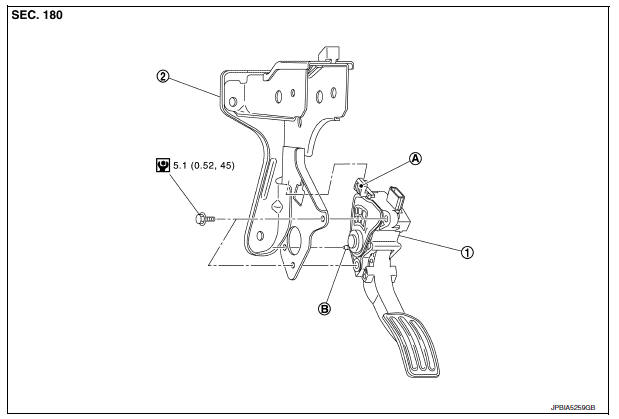
- Accelerator pedal assembly
- Brake pedal bracket
- Locating hook
- Locating pin
Removal and Installation
REMOVAL
- Remove instrument lower panel LH. Refer to IP-21, "Removal and Installation".
- Disconnect the harness connector From the accelerator pedal assembly.
- Loosen bolts and remove accelerator pedal assembly.
CAUTION:
- Do not disassemble accelerator pedal assembly.
- Do not remove accelerator pedal position sensor from accelerator pedal assembly.
- Do not drop or impact the accelerator pedal assembly.
- Do not expose the accelerator pedal assembly to water.
INSTALLATION
Installation is in the reverse order of removal.
- Insert the locating hook and pin into the brake pedal bracket.
CAUTION:
Do not squeeze the locating hook into the brake pedal bracket when inserting the locating pin into the hole on the brake pedal bracket side.
Inspection
INSPECTION AFTER INSTALLATION
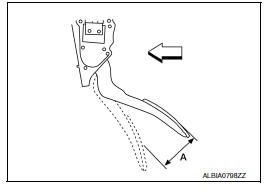
- Check that the accelerator pedal moves smoothly within the specified range.
Accelerator pedal stroke (A) : Refer to ACC-5, "Accelerator Control"
- For the electrical inspection of accelerator pedal position sensor. Refer to EC-138, "Work Procedure".
CAUTION:
- Whenever the harness connector of accelerator pedal position sensor is disconnected, perform “ACCELERATOR PEDAL RELEASED POSITION LEARNING”. Refer to EC-138, "Work Procedure".
- The accelerator pedal should return smoothly to the fully raised position.
 Precaution
Precaution for Supplemental Restraint System (SRS) "AIR BAG" and "SEAT
BELT PRE-TENSIONER"
The Supplemental Restraint System such as “AIR BAG” and “SEAT BELT PRE- ...
 Service data and specifications (SDS)
Accelerator Control
...
Other materials:
Front drive shaft
6M/T
6M/T : Exploded View (LH)
Front drive shaft
Nut retainer
Cotter pin
Molykote M77
Front
6M/T : Removal and Installation (LH)
NOTE:
When removing components such as hoses, tubes, lines, etc., cap or plug
openings to prevent fluid from spilling.
REMOVAL
Remove the ...
Voice Adaptation (VA) mode
Voice Adaptation allows up to two out-of-dialect
users to train the system to improve recognition
accuracy. By repeating a number of commands,
the users can create a voice model of their own
voice that is stored in the system. The system is
capable of storing a different voice adaptation
model ...
Combination meter
Reference Value
VALUES ON THE DIAGNOSIS TOOL
NOTE:
The following table includes information (items) inapplicable to this
vehicle. For information (items) applicable
to this vehicle, refer to CONSULT display items.
Note:
Some items are not available according to vehicle specificat ...
