Nissan Sentra Service Manual: Removal and installation
OIL COOLER
Exploded View
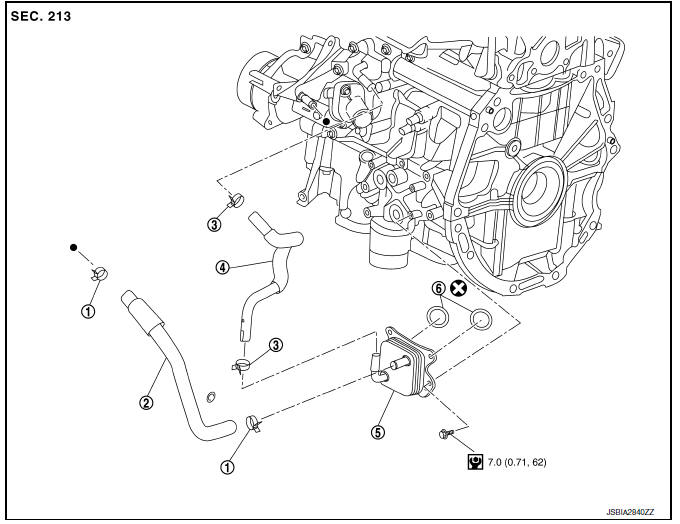
M/T models
- Clamp
- Water hose
- Clamp
- Water hose
- Oil cooler
- O-rings
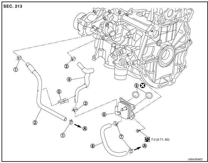
CVT models
- Clamp
- Water hose
- Clamp
- Water hose
- Water hose clip
- Oil cooler
- Clamp
- Water hose
- O-rings
- To CVT oil warmer
Removal and Installation
REMOVAL
- Remove engine under cover. Refer to EXT-16, "Exploded View".
- Drain engine coolant. Refer to CO-12, "Changing Engine Coolant".
CAUTION:
Perform when engine is cold.
- Remove water hoses.
- Remove bolts, oil cooler and O-rings.
CAUTION:
- Be careful not to get burned when engine and engine oil may be hot.
- When removing, prepare a shop cloth to absorb any engine oil leaks or spills.
- Completely wipe off any engine oil that adheres to engine and vehicle.
INSTALLATION
Installation is in the reverse order of removal.
CAUTION:
Do not reuse O-rings.
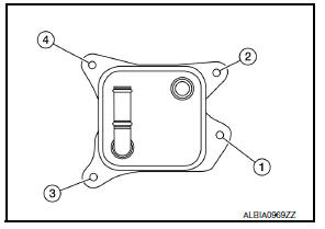
NOTE:
Tighten the oil cooler bolts in order as shown to specification.
Inspection
INSPECTION AFTER REMOVAL
Oil Cooler
Check oil cooler for cracks. Check oil cooler for clogging by blowing through engine coolant inlet. If necessary, replace oil cooler assembly.
INSPECTION AFTER INSTALLATION
- Check the engine oil level and the engine coolant level and add engine oil and engine coolant. Refer to LU-7, "Inspection" and CO-11, "System Inspection".
- Start the engine, and check that there are no leaks of engine oil or engine coolant.
- Stop the engine and wait for 10 minutes.
- Check the engine oil level and the engine coolant level again. Refer to LU-7, "Inspection" and CO-11, "System Inspection".
 Oil filter
Removal and Installation
REMOVAL
Remove engine under cover. Refer to EXT-16, "Exploded View".
Drain engine oil. Refer to LU-8, "Draining".
Remove the oil filter using Too ...
 Unit disassembly and assembly
OIL PUMP
O-ring
Oil pan (upper)
Oil level gauge guide
O-ring
Oil level gauge
Oil pump chain tensioner
Oil pump drive chain
Crankshaft sprocket
Oil pump sprocket
Oil pump
Dr ...
Other materials:
Door lock and unlock switch
Component function check
1.Check function
Select door lock of bcm using consult.
Select cdl lock sw, cdl unlock sw in data monitor mode.
Check that the function operates normally according to the following
conditions.
Is the inspection result normal?
YES >> Main power windo ...
On board diagnostic (OBD) system
Diagnosis Description
This system is an on board diagnostic system that records exhaust
emission-related diagnostic information
and detects a sensors/actuator-related malfunction. A malfunction is indicated
by the malfunction indicator
lamp (MIL) and stored in ECU memory as a DTC. The diagnos ...
Periodic maintenance
Introduction of periodic maintenance
The following tables show the normal maintenance schedule. Depending upon
weather and atmospheric conditions,
varying road surfaces, individual driving habits and vehicle usage, additional
or more frequent maintenance
may be required.
Periodic maintenan ...
