Nissan Sentra Service Manual: Unit disassembly and assembly
OIL PUMP
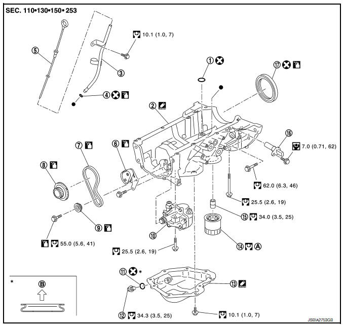
- O-ring
- Oil pan (upper)
- Oil level gauge guide
- O-ring
- Oil level gauge
- Oil pump chain tensioner
- Oil pump drive chain
- Crankshaft sprocket
- Oil pump sprocket
- Oil pump
- Drain plug washer
- Drain plug
- Oil pan (lower)
- Oil filter
- Connector bolt
- Crankshaft position sensor
- Rear oil seal
- Refer to LU-10, "Removal and Installation"
- Oil pan side
Removal and Installation
REMOVAL
- Remove engine under cover. Refer to EXT-16, "Exploded View".
- Remove air cleaner and air duct. Refer toEM-25, "Removal and Installation".
- Remove fender protector. Refer to EXT-28, "FENDER PROTECTOR : Removal and Installation - Front Fender Protector".
- Remove timing chain. Refer to EM-49, "Removal and Installation".
- Remove oil pump.
- Loosen bolts in reverse order as shown.
(1) : Oil pump
(2) : Oil pan (upper)
INSTALLATION
CAUTION:
Do not reuse O-rings or washers.
Installation is in the reverse order of removal.
Oil Pump
- Tighten bolts in numerical order as shown.
(1) : Oil pump
(2) : Oil pan (upper)
Inspection
INSPECTION AFTER INSTALLATION
- Check the engine oil level. Refer to LU-7, "Inspection".
- Start the engine, and check that there are no leaks of engine oil.
- Stop the engine and wait for 10 minutes.
- Check the engine oil level, and adjust the level. Refer to LU-7, "Inspection".
 Removal and installation
OIL COOLER
Exploded View
M/T models
Clamp
Water hose
Clamp
Water hose
Oil cooler
O-rings
CVT models
Clamp
Water hose
Clamp
Water hose
Water hose clip
Oil coole ...
 Service data and specifications
(SDS)
Service data and specifications
(SDS)
Oil pressure
*: Engine oil temperature at 80В°C (176В°F)
Oil Capacity
...
Other materials:
P1556, P1557 Battery temperature sensor
DTC Logic
DTC DETECTION LOGIC
NOTE:
If DTC P1556 or P1557 is displayed with DTC P0643, first perform the
trouble diagnosis for DTC P0643.
Refer to EC-353, "DTC Logic".
DTC No.
CONSULT screen terms
(Trouble diagnosis content)
DTC detecting condition
Possible caus ...
Precaution
Precaution for Supplemental Restraint System (SRS) "AIR BAG" and "SEAT
BELT PRE-TENSIONER"
The Supplemental Restraint System such as “AIR BAG” and “SEAT BELT PRE-TENSIONER”,
used along
with a front seat belt, helps to reduce the risk or severity of injur ...
P0604 ECM
DTC Logic
DTC DETECTION LOGIC
DTC No.
CONSULT screen terms
(Trouble diagnosis content)
DTC detecting condition
Possible cause
P0604
ECM
[Internal control module
random access memory
(RAM) error]
Malfunction in the internal RAM of ECM.
ECM
DTC CON ...
