
Nissan Sentra Service Manual: P1551, P1552 Battery current sensor
DTC Logic
DTC DETECTION LOGIC
| DTC No. | CONSULT screen terms (Trouble diagnosis content) | DTC detecting condition | Possible cause |
| P1551 | BAT CURRENT SENSOR (Battery current sensor) | An excessively low voltage from the sensor is sent to ECM. |
|
| P1552 | BAT CURRENT SENSOR (Battery current sensor) | An excessively high voltage from the sensor is sent to ECM. |
DTC CONFIRMATION PROCEDURE
1.PRECONDITIONING
If DTC Confirmation Procedure has been previously conducted, always perform the following before conducting the next test.
- Turn ignition switch OFF and wait at least 10 seconds.
- Turn ignition switch ON.
- Turn ignition switch OFF and wait at least 10 seconds.
TESTING CONDITION:
Before performing the following procedure, confirm that battery voltage is more than 8 V with ignition switch ON
>> GO TO 2.
2.PERFORM DTC CONFIRMATION PROCEDURE
- Turn ignition switch ON and wait at least 10 seconds.
- Check 1st trip DTC.
Is 1st trip DTC detected? YES >> Proceed to EC-377, "Diagnosis Procedure".
NO >> INSPECTION END
Diagnosis Procedure
1.CHECK BATTERY CURRENT SENSOR POWER SUPPLY
- Turn ignition switch OFF.
- Disconnect battery current sensor harness connector.
- Turn ignition switch ON.
- Check the voltage between battery current sensor harness connector and ground.
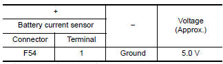
Is the inspection result normal? YES >> GO TO 3.
NO >> GO TO 2.
2.CHECK SENSOR POWER SUPPLY 2 CIRCUIT
Check sensor power supply 2 circuit. Refer to EC-444, "Diagnosis Procedure".
Is the inspection result normal? YES >> Perform the trouble diagnosis for power supply circuit.
NO >> Repair or replace error-detected parts.
3.CHECK BATTERY CURRENT SENSOR GROUND CIRCUIT
- Turn ignition switch OFF.
- Disconnect ECM harness connector
- Check the continuity between battery current sensor harness connector and ECM harness connector.
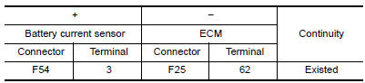
- Also check harness for short to power.
Is the inspection result normal? YES >> GO TO 4.
NO >> Repair or replace error-detected parts.
4.CHECK BATTERY CURRENT SENSOR INPUT SIGNAL CIRCUIT
- Check the continuity between battery current sensor harness connector and ECM harness connector.
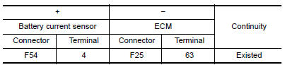
- Also check harness for short to ground and to power.
Is the inspection result normal? YES >> GO TO 5.
NO >> Repair or replace error-detected parts
5.CHECK BATTERY CURRENT SENSOR
Check the battery current sensor. Refer to EC-378, "Component Inspection (Battery Current Sensor)".
Is the inspection result normal? YES >> Check intermittent incident. Refer to GI-39, "Intermittent Incident".
NO >> Replace battery current sensor. Refer to PG-53, "Removal and Installation".
Component Inspection (Battery Current Sensor)
1.CHECK BATTERY CURRENT SENSOR
- Turn ignition switch OFF.
- Reconnect harness connectors disconnected.
- Disconnect battery negative cable.
- Install jumper cable between battery negative terminal and body ground.
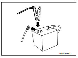
- Turn ignition switch ON.
- Check the voltage between ECM harness connector terminals.
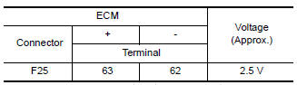
Before measuring the terminal voltage, confirm that the battery is fully charged. Refer to PG-4, "How to Handle Battery".
Is the inspection result normal? YES >> INSPECTION END
NO >> Replace battery current sensor. Refer to PG-53, "Removal and Installation".
 P1550 Battery current sensor
DTC Logic
DTC DETECTION LOGIC
DTC No.
CONSULT screen terms
(Trouble diagnosis content)
DTC detecting condition
Possible cause
P1550
BAT CURRENT SENSOR
(Battery curr ...
 P1553 Battery current sensor
DTC Logic
DTC DETECTION LOGIC
DTC No.
CONSULT screen terms
(Trouble diagnosis content)
DTC detecting condition
Possible cause
P1553
BAT CURRENT SENSOR
(Battery curr ...
Other materials:
Rear disc brake
BRAKE PAD
BRAKE PAD : Inspection
PAD WEAR
Check pad thickness from an inspection hole on caliper body. Check
using a scale if necessary.
Wear limit thickness : Refer to BR-55, "Rear Disc
Brake".
DISC ROTOR
DISC ROTOR : Inspection
APPERANCE
Check surface of disc rotor for unev ...
C1729 Vehicle speed signal
DTC Logic
NOTE:
The Signal Tech II Tool (J-50190) can be used to perform the following
functions. Refer to the Signal Tech II
User Guide for additional information.
Activate and display TPMS transmitter IDs
Display tire pressure reported by the TPMS transmitter
Read TPMS DTCs
Registe ...
System
EPS system
EPS SYSTEM : System Description
SYSTEM DIAGRAM
DESCRIPTION
EPS control unit performs an arithmetical operation on data,
such
as steering wheel turning force (sensor signal) from the torque
sensor, vehicle speed signal, etc. Then it generates an optimum
assist torque ...
