Nissan Sentra Service Manual: Intake manifold tuning system
INTAKE MANIFOLD TUNING SYSTEM : System Description
SYSTEM DIAGRAM
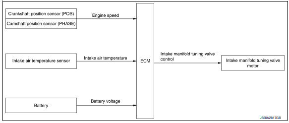
SYSTEM DESCRIPTION
This system switches the length of intake air path according to the low-to-medium speed range or high speed range. Torque is increased in the low-to-medium speed range and the engine output is improved in the high speed range.
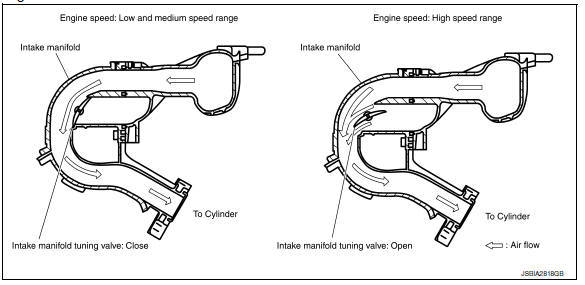
Engine speed: Low and medium speed range
Since the intake manifold tuning (IMT) valve is closed when the engine speed is less than 5,250 rpm, the length of the effective intake air path is from the mouth of intake manifold collector to the intake valve. This long path brings the inertia effect of intake air, contributing to the improvement in intake air efficiency and the generation of high torque.
Engine speed: High speed range
When engine speed is 5,250 rpm or more, ECM turns ON the intake manifold tuning valve motor to open the intake manifold tuning valve. The length of the effective intake air path at this time is from the intake manifold tuning valve to the intake valve. This short path brings the inertia effect of intake air in the high speed range, contributing to the torque improvement while the engine is running at high speeds. (The highest engine output is improved.)
Intake Manifold Tuning Valve Operating Condition
ECM opens the intake manifold tuning valve when all of the following conditions are satisfied.
- Engine speed: 5,250 rpm or more
- Engine coolant temperature: -30В°C (-22В°F) or more
- Battery voltage: between 11 V and 16 V
 Intake manifold runner control
INTAKE MANIFOLD RUNNER CONTROL : System
Description
SYSTEM DIAGRAM
SYSTEM DESCRIPTION
Intake manifold runner control valve has a valve portion in the intake
passage of each cylinder.
Whil ...
 Engine protection control at low engine
oil pressure
Engine protection control at low engine
oil pressure
ENGINE PROTECTION CONTROL AT LOW ENGINE OIL PRESSURE : System Description
SYSTEM DIAGRAM
INPUT/OUTPUT SIGNAL CHART
Sensor
Input signal to ECM
ECM function
Actuator
Engi ...
Other materials:
DTC/circuit diagnosis
U1000 CAN COMM CIRCUIT
Description
Refer to lan-7, "can communication system : system description".
Dtc logic
Dtc detection logic
Note:
U1000 can be set if a module harness was disconnected and reconnected,
perhaps during a repair. Confirm
that there are actual CAN diagnostic symp ...
P0075 IVT control solenoid valve
DTC Logic
DTC DETECTION LOGIC
DTC No.
CONSULT screen terms
(Trouble diagnosis content)
DTC detecting condition
Possible cause
P0075
INT/V TIM V/CIR-B1
(Intake valve control solenoid
circuit bank 1)
An improper voltage is sent to the ECM
through intake val ...
Service data and specifications (SDS)
General Specifications
Clutch Pedal
Clutch Disc
Clutch Cover
...
