
Nissan Sentra Service Manual: Fuel level sensor signal circuit
Description
The fuel level sensor unit and fuel pump detects the approximate fuel level in the fuel tank and transmits the fuel level signal to the combination meter.
Component function check
1.Combination meter input signal
- Select meter/m&a on consult.
- Using FUEL METER of DATA MONITOR, compare the value of DATA MONITOR with fuel gauge pointer of combination meter.
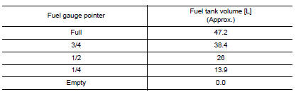
Does the data monitor value approximately match the fuel gauge indication? YES >> Inspection End.
NO >> Replace combination meter. Refer to MWI-77, "Removal and Installation".
Diagnosis procedure
Regarding wiring diagram information, refer to mwi-28, "wiring diagram".
1.Check fuel level sensor circuit
- Turn ignition switch off.
- Disconnect combination meter connector and fuel level sensor unit connector.
- Check continuity between combination meter harness connector and fuel level sensor unit harness connector.

- Check continuity between combination meter harness connector and ground.

Is the inspection result normal? Yes >> go to 2.
No >> repair or replace harness or connector.
2.Check fuel level sensor ground circuit
- Check continuity between fuel level sensor unit harness connector and combination meter harness connector.

- Check continuity between combination meter harness connector and ground.

Is the inspection result normal? YES >> GO TO 3.
NO >> Repair or replace harness or connector.
3.Check installation condition
Check fuel level sensor unit installation, and check whether the float arm interferes or binds with any of the internal components in the fuel tank.
Is the inspection result normal? Yes >> inspection end.
No >> install the fuel level sensor unit properly. Refer to fl-6, "removal and installation".
Component inspection
1.Remove fuel level sensor unit
Remove the fuel level sensor unit. Refer to fl-6, "removal and installation".
>> Go to 2.
2.Check fuel level sensor unit
Check the resistance between fuel level sensor unit and fuel pump.
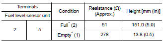
*: When float rod is in contact with stopper.
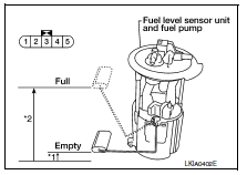
Is inspection result ok? Yes >> inspection end.
No >> replace fuel level sensor unit and fuel pump. Refer to fl-6, "removal and installation".
 Illumination control switch signal circuit
Diagnosis procedure
Regarding wiring diagram information, refer to mwi-28, "wiring diagram".
1.Check combination meter input signal
Turn ignition switch on.
Check voltage between the ...
 Parking brake switch signal circuit
Component function check
1.Check parking brake switch operation
Check that brake warning lamp in combination meter turns on/off when parking
brake is actuated.
Is the inspection result normal?
...
Other materials:
B00D5 Passenger air bag OFF Indicator
Description
DTC B00D5 FRONT PASSENGER AIR BAG OFF INDICATOR
The front passenger air bag off indicator is wired to the air bag diagnosis
sensor unit. The air bag diagnosis
sensor unit monitors the front passenger air bag off indicator and circuit for
failures.
PART LOCATION
Refer to SRC-5, ...
Service data and specifications
(sds)
General Specification
Drive Belt
Spark Plug
*:Always check with the Parts Department for the latest parts information.
Exhaust Manifold
Camshaft
VALVE LIFTER
VALVE CLEARANCE
*: Approximately 80В°C (176В°F)
AVAILABLE VALVE LIFTER
*:Always check with the P ...
Precaution for supplemental restraint system (srs) "air bag" and "seat belt
pre-tensioner"
The Supplemental Restraint System such as “AIR BAG” and “SEAT BELT PRE-TENSIONER”,
used along
with a front seat belt, helps to reduce the risk or severity of injury to the
driver and front passenger for certain
types of collision. Information necessary to service the system ...
