Nissan Sentra Service Manual: Illumination control switch signal circuit
Diagnosis procedure
Regarding wiring diagram information, refer to mwi-28, "wiring diagram".
1.Check combination meter input signal
- Turn ignition switch on.
- Check voltage between the following terminals of the illumination control switch.
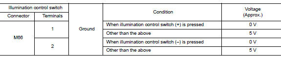
Is the inspection result normal? YES >> Inspection End.
NO >> GO TO 2.
2.Check illumination control switch signal circuit
- Turn ignition switch off
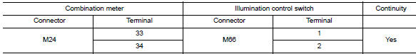
- Disconnect combination meter connector m24 and illumination control switch connector m66.
- Check continuity between combination meter harness connector and illumination control switch harness connector.
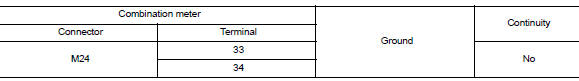
- Check continuity between combination meter harness connector and ground.
Is the inspection result normal? Yes >> check illumination control switch. Refer to mwi-56, "component inspection".
No >> repair or replace harness or connector.
Component inspection
1.Check illumination control switch
- Turn ignition switch OFF.
- Disconnect illumination control switch connector.
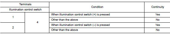
- Check illumination control switch.
Is the inspection result normal? Yes >> inspection end.
No >> replace illumination control switch. Refer to mwi-80, "removal and installation".
 Steering switch (meter control switch) signal circuit
Diagnosis Procedure
Regarding wiring diagram information, refer to mwi-28, "wiring diagram".
1.Check combination meter input signal
Turn ignition switch on.
Measure voltage between ...
 Fuel level sensor signal circuit
Description
The fuel level sensor unit and fuel pump detects the approximate fuel level
in the fuel tank and transmits the
fuel level signal to the combination meter.
Component function check
1 ...
Other materials:
B0001, B0002 Driver airbag module
Description
DTC B0001, B0002 DRIVER AIRBAG MODULE
The driver air bag module is dual stage and is wired to the air bag diagnosis
sensor unit through the spiral
cable. The air bag diagnosis sensor unit will monitor for opens and shorts in
detected lines to the driver air bag
module including t ...
Bluetooth® settings
To access the phone settings:
Press the [ ] button.
Touch the “Settings” key.
Touch the “Phone & Bluetooth” key.
Menu Item
Result
Phone Settings
See “Phone settings” in this section for more information.
Connect New Device
Touch to co ...
1144 Incomplete steering angle sensor adjustment
DTC Logic
Dtc detection logic
Dtc
Display item
Malfunction detected condition
Possible causes
C1144
St ang sen signal
When neutral position adjustment of steering angle
sensor is not complete.
Harness or connector
Steering angle sensor
Abs actu ...
