Nissan Sentra Service Manual: Disassembly and assembly
FUEL LEVEL SENSOR UNIT
Exploded View
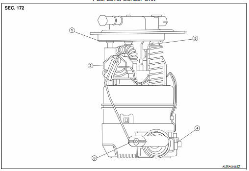
Fuel Level Sensor Unit
- Fuel filter and pump assembly
- Fuel level sensor unit
- Float arm assembly
- Fuel tank temperature sensor
- Fuel level sensor unit/fuel tank temperature sensor harness connector
Disassembly and Assembly
DISASSEMBLY
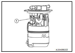
- Disconnect fuel level sensor unit/fuel tank temperature sensor harness connector (1).
NOTE:
Hold connector with your fingers, because there is no tab for releasing stopper. Pull it out straight downward.
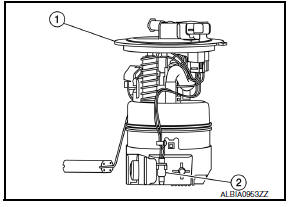
- Remove fuel tank temperature sensor (2) from fuel filter and fuel pump assembly (1).
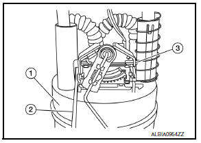
- Using a suitable tool (2), remove fuel level sensor unit (3) from fuel filter and fuel pump assembly (1).
CAUTION:
- Be careful not to damage the fuel level sensor unit.
- Do not disassemble fuel filter and fuel pump assembly.
ASSEMBLY
- Check for damage of fuel level sensor unit installation position on the side of fuel filter and pump assembly.
- Slide fuel level sensor unit until it aligns to installation groove, then insert it until it stops.
- After inserting, apply force in reverse direction (removal direction) to ensure it cannot be pulled out.
- Connect fuel level sensor unit/fuel tank temperature sensor harness connector.
INSPECTION AFTER INSTALLATION
Use the following procedure to check for fuel leaks.
- Turn ignition switch “ON” (with engine stopped), then check connections for leaks by applying fuel pressure to fuel piping.
- Start engine and let it idle and check there are no fuel leaks at the fuel system connections.
 Evap canister
Exploded View
EVAP canister bracket
EVAP canister filter drain hose
EVAP canister filter
EVAP canister protector
EVAP hose
EVAP canister vent control valve
O-ring
EVAP canister
...
 Service data and specifications (SDS)
Fuel Tank
Standard and Limit
Standard and Limit
...
Other materials:
Component parts
Component Parts Location
BCM (view with instrument panel removed)
Remote keyless entry receiver (view
with instrument panel removed)
Transmitter
Combination meter
Component Description
BCM
The BCM reads the tire pressure signal received by the remote keyless entry
receiver ...
Wiring diagram
CVT Control system
Wiring Diagram
CVT Shift lock system
Wiring Diagram
...
P2138 APP Sensor
DTC Logic
DTC DETECTION LOGIC
NOTE:
If DTC P2138 is displayed with DTC P0643, first perform the trouble
diagnosis for DTC P0643. Refer to
EC-353, "DTC Logic".
DTC No.
CONSULT screen terms
(Trouble diagnosis content)
DTC detecting condition
Possible cause
...
