Nissan Sentra Service Manual: Diagnosis system [abs actuator and electric unit (control unit)]
CONSULT Function (ABS)
FUNCTION
CONSULT can display each diagnostic item using the following direct diagnostic modes.
| Direct Diagnostic Mode | Description |
| ECU identification | The ABS actuator and electric unit (control unit) part number is displayed. |
| Self Diagnostic Result | The ABS actuator and electric unit (control unit) self diagnostic results are displayed. |
| Data Monitor | The ABS actuator and electric unit (control unit) input/output data is displayed in real time. |
| Active Test | The ABS actuator and electric unit (control unit) activates outputs to test components. |
| Work support | The settings for ABS actuator and electric unit (control unit) functions can be changed. |
| CAN DIAG SUPPORT MNTR | The result of transmit/receive diagnosis of CAN communication is displayed. |
ECU IDENTIFICATION
ABS actuator and electric unit (control unit) part number is displayed.
SELF DIAGNOSTIC RESULT
Operation Procedure
-
Before performing the self-diagnosis, start engine and drive vehicle at 30 km/h (19 MPH) or more for approximately 1 minute.
How To Erase Self Diagnostic Result
-
After erasing DTC memory, start engine and drive vehicle at 30 km/h (19 MPH) or more for approximately 1 minute as the final inspection, and make sure that the ABS warning lamp, VDC OFF indicator lamp, SLIP indicator lamp and brake warning lamp turn OFF.
CAUTION:
If memory cannot be erased, perform applicable diagnosis.
NOTE:
-
When the wheel sensor malfunctions, after inspecting the wheel sensor system, the ABS warning lamp, SLIP indicator lamp and brake warning lamp will not turn OFF even when the system is normal, unless the vehicle is driven at approximately 30 km/h (19 MPH) or more for approximately 1 minute.
-
Brake warning lamp will turn ON in case of parking brake operation (when switch is ON) or of brake fluid level switch operation (when brake fluid is insufficient).
-
VDC OFF switch should not stay in ON position.
Display Item List
Refer to BRC-43, "DTC Index".
DATA MONITOR
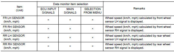
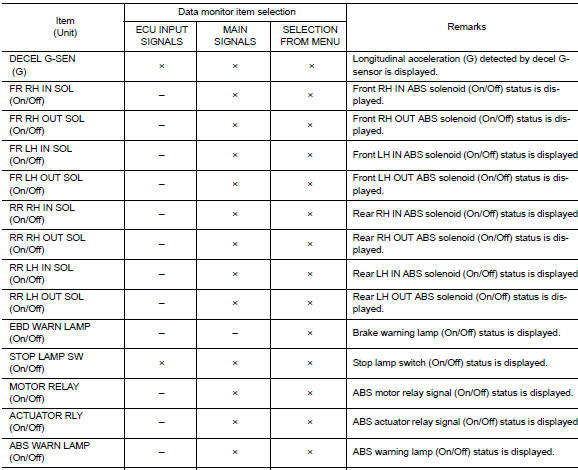
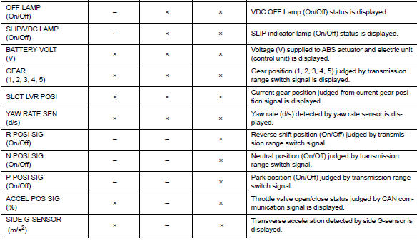
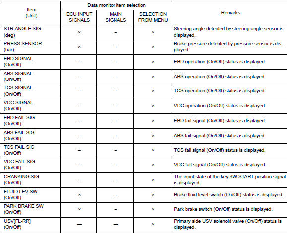
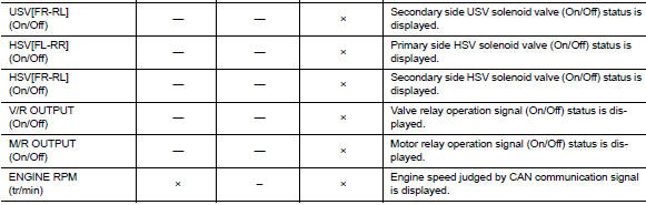
×: Applicable
–: Not applicable
ACTIVE TEST
The active test is used to determine and identify details of a malfunction, based on self-diagnosis test results and data obtained in the DATA MONITOR. In response to instructions from CONSULT, instead of those from ABS actuator and electric unit (control unit) on the vehicle, a drive signal is sent to the actuator to check its operation.
CAUTION:
-
Never perform ACTIVE TEST while driving the vehicle.
-
Always bleed air from brake system before active test.
-
Never perform active test when system is malfunctioning.
NOTE:
-
When active test is performed while depressing the pedal, the pedal depressing stroke may change. This is not a malfunction.
-
“TEST IS STOPPED” is displayed approx. 10 seconds after operation start.
-
When performing active test again after “TEST IS STOPPED” is displayed, select “BACK”.
-
ABS warning lamp, brake warning lamp and VDC warning lamp may turn ON during active test. This is not a malfunction.
ABS IN Valve and ABS OUT Valve
When “Up”, “Keep” or “Down” is selected on display screen, the following items are displayed when system is normal.
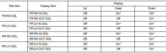
*: Immediately after being selected, status is “On”. Status changes to “Off” after approx. 2 seconds.
ABS IN Valve (ACT) and ABS OUT Valve (ACT)
When “Up”, “ACT UP” or “ACT KEEP” is selected on display screen, the following items are displayed when system is normal.
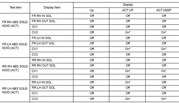
*: Immediately after being selected, status is “On”. Status changes to “Off” after approx. 10 seconds.
ABS Motor
When “On” or “Off” is selected on display screen, the following items are displayed when system is normal.
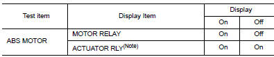
NOTE:
Display occasionally changes On/Off for a moment after ignition switch is turned ON. This is an operation for checking purposes and is not a malfunction.
WORK SUPPORT
| Conditions | Description |
| ST ANGLE SENSOR ADJUSTMENT | Steering angle sensor neutral position adjustment can be performed.
Refer to BRC-54, "Work Procedure". |
 System
VDC/TCS/ABS
VDC/TCS/ABS : System Diagram
VDC/TCS/ABS : System Description
The system switches fluid pressure of each brake caliper and
each wheel cylinder to increase, to hold, or to
...
 Ecu diagnosis information
Abs actuator and electric unit
(control unit)
Reference Value
VALUES ON THE DIAGNOSIS TOOL
CAUTION:
The display shows the control unit calculation data, so a
normal value might be displayed ev ...
Other materials:
C1609 Vehicle speed signal
DTC Logic
Dtc detection logic
DTC
Display item
Malfunction detected condition
Possible cause
C1609
CAN VHCL SPEED
Malfunction is detected in vehicle speed signal that
is output from abs actuator and electric unit (control
unit) via can communication. ...
Precaution
Precaution for Supplemental Restraint System (SRS) "AIR BAG" and "SEAT
BELT PRE-TENSIONER"
The Supplemental Restraint System such as “AIR BAG” and “SEAT BELT PRE-TENSIONER”,
used along
with a front seat belt, helps to reduce the risk or severity of injur ...
Wiring diagram
Headlamp
Wiring diagram
Daytime light system
Wiring diagram
Auto light system
Wiring diagram
Front fog lamp
Wiring diagram
Turn signal and hazard warning lamps
Wiring diagram
...
