
Nissan Sentra Service Manual: Connector symbols
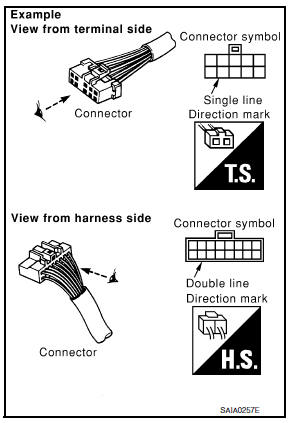
Most of connector symbols in wiring diagrams are shown from the terminal side.
- Connector symbols shown from the terminal side are enclosed by a single line and followed by the direction mark.
- Connector symbols shown from the harness side are enclosed by a double line and followed by the direction mark.
- Certain systems and components, especially those related to
OBD, may use a new style slide-locking type harness connector.
For description and how to disconnect, refer to PG section, “Description”, “HARNESS CONNECTOR”.
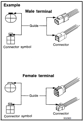
- Male and female terminals
Connector guides for male terminals are shown in black and female terminals in white in wiring diagrams.

 Sample/wiring diagram -example-
For detail, refer to following GI-11, "Description".
...
Other materials:
Symptom diagnosis
Push-button ignition switch does not operate
Description
Check that vehicle is under the condition shown in “Conditions of vehicle”
before starting diagnosis, and check
each symptom.
Note:
The engine start function, door lock function, power distribution system,
and nats-ivis/nvis ...
Additional service when replacing ecm
Description
When replacing ECM, the following procedure must be performed. (For details,
refer to EC-135, "Work Procedure".)
PROGRAMMING OPERATION
NOTE:
After replacing with a blank ECM, programming is required to write ECM
information. Be sure to follow the procedure
to perform t ...
Brake warning lamp
Component Function Check
1.CHECK BRAKE WARNING LAMP FUNCTION (1)
Check that brake warning lamp in combination meter turns ON for
approximately 2 seconds after ignition
switch is turned ON.
Is the inspection result normal?
YES >> GO TO 2.
NO >> Proceed to diagnosis procedure. ...
