
Nissan Sentra Service Manual: Hazard switch
Component function check
1.Check hazard switch signal by consult
 Consult data monitor
- Turn ignition switch ON.
- Select hazard sw of bcm (flasher) data monitor item.
- While operating the hazard switch, check the monitor status.

Is the inspection result normal? Yes >> hazard switch circuit is normal.
No >> refer to exl-105, "diagnosis procedure".
Diagnosis procedure
Regarding wiring diagram information, refer to exl-58, "wiring diagram".
1.Check hazard switch signal input
- Turn ignition switch off.
- Disconnect hazard switch connector.
- Turn ignition switch on
- Check voltage between hazard switch harness connector and ground.
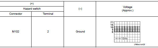
Is the inspection result normal? YES >> GO TO 4.
NO >> GO TO 2.
2.Check hazard switch signal open circuit
- Turn ignition switch off.
- Disconnect BCM connector.
- Check continuity between hazard harness connector and bcm harness connector.

Is the inspection result normal? Yes >> go to 3.
No >> repair or replace harness or connector.
3.Check hazard switch signal short circuit
Check continuity between hazard switch harness connector and ground.

Is the inspection result normal? YES >> Replace BCM. Refer to BCS-73, "Removal and Installation" (with Intelligent Key system) or BCS- 126, "Removal and Installation" (without Intelligent Key system).
NO >> Repair or replace harness or connector.
4.Check hazard switch ground open circuit
Check continuity between hazard switch harness connector and ground.

Is the inspection result normal? Yes >> replace hazard switch. Refer to exl-129, "removal and installation".
No >> repair or replace harness or connector.
 Optical sensor
Description
The optical sensor measures ambient light and transmits the optical sensor
signal to the bcm.
Component function check
1.Check optical sensor signal by consult
Consult
Turn the ...

Other materials:
The low washer fluid warning lamp does not turn on or off
Description
The low washer fluid warning lamp is still illuminated even after washer
fluid is added.
The low washer fluid warning lamp is not illuminated even though the
washer tank is empty.
Diagnosis procedure
1.Check washer fluid level switch signal circuit
Check the washer fluid ...
Under cover
Front under cover
Front under cover : removal and installation
REMOVAL
Remove front side of front fender protector (LH/RH). Refer to EXT-28,
"FENDER PROTECTOR : Removal
and Installation - Front Fender Protector".
Remove engine under cover. EXT-31, "ENGINE UNDER COVER : Re ...
Air cleaner filter
Exploded View
Mass air flow sensor
Mass air flow gasket
Clamp
Air duct (suction side)
Resonator
Clamp
PCV hose
Clamp
Clamp
Air cleaner cover
Mounting rubber
Air cleaner filter
Air cleaner body
Air duct inlet (lower)
Air duct inlet (upper)
Grommet
Bracket
Gro ...
