Nissan Sentra Service Manual: Charging system preliminary inspection
Diagnosis Procedure
1.CHECK BATTERY TERMINALS CONNECTION
Check if battery terminals are clean and tight.
Is the inspection result normal? YES >> GO TO 2.
NO >> Repair battery terminal connection. Confirm repair by performing complete Charging system test using EXP-800 NI or GR8-1200 NI (if available). Refer to the applicable Instruction Manual for proper testing procedures.
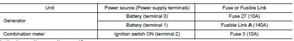
2.Check fuse
Check for blown fuse and fusible link.
Is the inspection result normal? Yes >> go to 3.
No >> replace the blown fuse or fusible link after repairing the affected circuit.
3.Check generator ground terminal connection
Check if connector f17 terminal 5 and 6 is clean.
Is the inspection result normal? Yes >> go to 4.
No >> repair connection.
4.Check drive belt tension
Check drive belt tension. Refer to chg-29, "removal and installation".
Is the inspection result normal? Yes >> inspection end.
No >> repair as needed.

 Power generation voltage variable control system operation inspection
Diagnosis Procedure
Regarding wiring diagram information. Refer to chg-9, "wiring diagram".
Caution:
When performing this inspection, always use a charged battery that has
completed the ...
Other materials:
Eps branch line circuit
Diagnosis procedure
1.Check connector
Turn the ignition switch off.
Disconnect the battery cable from the negative terminal.
Check the terminals and connectors of the eps control unit for damage,
bend and loose connection (unit
side and connector side).
Is the inspection result norm ...
Help voice commands
The following voice commands can be spoken to
have the system provide instructions and tips for
using the NISSAN Voice Recognition system.
List Commands
What Can I Say?
General Help
Quit
Exit
Symptom/error message
Solution
The system responds ŌĆ£Command Not
Rec ...
Child safety rear door lock
Child safety locks help prevent the rear doors
from being opened accidentally, especially when
small children are in the vehicle.
The child safety lock levers are located on the
edge of the rear doors.
When the lever is in the unlock position 2 , the
door can be opened from the outside ...
