Nissan Sentra Service Manual: C1143 Steering angle sensor
DTC Logic
DTC DETECTION LOGIC
| DTC | Display Item | Malfunction detected condition | Possible causes |
| C1143 | ST ANG SEN CIRCUIT | When a malfunction is detected in steering angle sensor. |
|
DTC CONFIRMATION PROCEDURE
1.CHECK SELF DIAGNOSTIC RESULT
 With CONSULT
-
Turn ignition switch ON.
-
Perform self diagnostic result.
Is DTC C1143 detected? YES >> Proceed to diagnosis procedure. Refer to BRC-80, "Diagnosis Procedure".
NO >> Inspection End.
Diagnosis Procedure
Regarding Wiring Diagram information, refer to BRC-44, "Wiring Diagram".
1.CONNECTOR INSPECTION
-
Turn ignition switch OFF.
-
Disconnect ABS actuator and electric unit (control unit) and steering angle sensor connectors.
-
Check connectors and terminals for deformation, disconnection, looseness or damage.
Is the inspection result normal? YES >> GO TO 2.
NO >> Repair or replace as necessary.
2.CHECK STEERING ANGLE SENSOR MOUNTING CONDITION
Check steering angle sensor mounting condition.
Is the inspection result normal? YES >> GO TO 3.
NO >> Repair or replace malfunctioning components.
3.Check steering angle sensor power supply
-
Turn ignition switch OFF.
-
Disconnect steering angle sensor connector.
-
Turn ignition switch ON.
-
Check voltage between steering angle sensor connector M14 terminal 4 and ground.
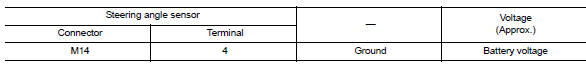
Is the inspection result normal? Yes >> go to 4.
No >> check the following:
-
Repair or replace harness.
-
Fuse
4.Check steering angle sensor ground circuit
-
Turn ignition switch off.
-
Check continuity between steering angle sensor connector m14 terminal 1 and ground.
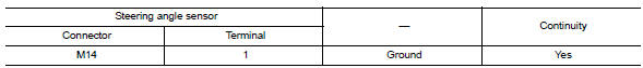
Is the inspection result normal? Yes >> go to 5.
No >> repair or replace malfunctioning components.
5.Check can communication line
Check “strg branch line circuit”. Refer to lan-66, "diagnosis procedure" (type 1) or lan-79, "diagnosis procedure" (type 2).
Is the inspection result normal? Yes >> replace abs actuator and electric unit (control unit). Refer to brc-110, "removal and installation".
No >> repair or replace malfunctioning components.
 C1142 Press sensor
DTC Logic
DTC DETECTION LOGIC
DTC
Display Item
Malfunction detected condition
Possible causes
C1142
PRESS SEN CIRCUIT
When a malfunction is detected in master cylinde ...
 1144 Incomplete steering angle sensor adjustment
DTC Logic
Dtc detection logic
Dtc
Display item
Malfunction detected condition
Possible causes
C1144
St ang sen signal
When neutral position adjustment of steering angl ...
Other materials:
NISSAN Intelligent Key® battery discharge
If the battery of the NISSAN Intelligent Key® is
discharged, or environmental conditions interfere
with the Intelligent Key operation, start the engine
according to the following procedure:
Place the shift lever in the P (Park) position.
Firmly apply the foot brake.
Touch the ignitio ...
System
SRS air bag system
SRS AIR BAG SYSTEM : System Diagram
SRS AIR BAG SYSTEM : System Description
The air bag deploys if the air bag diagnosis sensor unit is activated
while the ignition switch is in the ON or
START position.
The collision modes for which supplemental restraint systems ...
Both doors mirror defogger don’t operate but rear window defogger operates
Diagnosis procedure
Regarding Wiring Diagram information, refer to DEF-20, "Wiring Diagram".
1. Check door mirror defogger fuse
Check if the following fuse in fuse block (J/B) is blown.
Is the inspection result normal?
Yes >> go to 2.
No >> replace the blown fuse af ...
