Nissan Sentra Service Manual: C1115 ABS Sensor [abnormal signal]
DTC Logic
DTC DETECTION LOGIC
| DTC | Display Item | Malfunction detected condition | Possible causes |
| C1115 | ABS SENSOR [ABNORMAL SIGNAL] | When difference in wheel speed between any wheel and others is detected while the vehicle is driven, because of installation of tires other than specified. |
|
DTC CONFIRMATION PROCEDURE
1.CHECK SELF DIAGNOSTIC RESULT
 With CONSULT
-
Start engine and drive vehicle at approximately 30 km/h (19 MPH) or more for approximately 1 minute.
-
Perform self diagnostic result.
Is DTC C1115 detected? YES >> Proceed to diagnosis procedure. Refer to BRC-68, "Diagnosis Procedure".
NO >> Inspection End.
Diagnosis Procedure
Regarding Wiring Diagram information, refer to BRC-44, "Wiring Diagram".
CAUTION:
Do not check between wheel sensor terminals.
1.CONNECTOR INSPECTION
-
Disconnect ABS actuator and electric unit (control unit) connector E33 and wheel sensor connector of wheel with DTC.
-
Check terminals for deformation, disconnection, looseness or damage.
Is the inspection result normal? YES >> GO TO 2.
NO >> Repair or replace as necessary.
2.CHECK WHEEL SENSOR OUTPUT SIGNAL
-
Connect ABS active wheel sensor tester (J-45741) to wheel sensor using appropriate adapter
-
Turn on the ABS active wheel sensor tester power switch.
NOTE:
The green POWER indicator should illuminate. If the POWER indicator does not illuminate, replace the battery in the ABS active wheel sensor tester before proceeding.
-
Spin the wheel of the vehicle by hand and observe the red SENSOR indicator on the ABS active wheel sensor tester. The red SENSOR indicator should flash on and off to indicate an output signal.
NOTE:
If the red SENSOR indicator illuminates but does not flash, reverse the polarity of the tester leads and retest.
Does the ABS active wheel sensor tester detect a signal? YES >> GO TO 3.
NO >> Replace the wheel sensor. Refer to BRC-106, "FRONT WHEEL SENSOR : Removal and Installation" or BRC-107, "REAR WHEEL SENSOR : Removal and Installation".
3.CHECK TIRES
Check the inflation pressure, wear and size of each tire.
Is the inspection result normal?
YES >> GO TO 4.
NO >> Adjust tire pressure, or replace tire(s).
4.Check wiring harness for short circuit
Check continuity between wheel sensor connector terminals and ground of wheel with DTC.
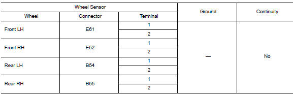
Is the inspection result normal? YES >> GO TO 5.
NO >> Repair the circuit.
5.Check wiring harness for open circuit
Check continuity between ABS actuator and electric unit (control unit) connector E33 and wheel sensor connector of wheel with DTC.
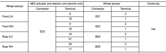
Is the inspection result normal? YES >> Replace the ABS actuator and electric unit (control unit). Refer to BRC-110, "Removal and Installation".
NO >> Repair the circuit.
 C1113, C1145, C1146 Yaw rate/side/decel G Sensor
DTC Logic
DTC DETECTION LOGIC
DTC
Display Item
Malfunction detected condition
Possible causes
C1113
G SENSOR
When a malfunction is detected in longitunal G sensor
s ...
 C1116 Stop lamp switch
DTC Logic
DTC DETECTION LOGIC
DTC
Display item
Malfunction detected condition
Possible cause
C1116
STOP LAMP SW
When stop lamp switch circuit is open.
Harn ...
Other materials:
Wiring diagram
Power distribution system
Wiring diagram
...
Tire chains
CAUTION
Tire chains/cables should not be installed
on P205/50R17 size tires. Installation of
the tire chains/cables on P205/50R17 size
tires will cause damage to the vehicle. If
you plan to use tire chains/cables, you
should install P205/55R16 size tires on
your vehicle.
Use of tire chains m ...
Seat belt maintenance
To clean the seat belt webbing, apply a
mild soap solution or any solution recommended
for cleaning upholstery or carpet.
Then wipe with a cloth and allow the seat
belts to dry in the shade. Do not allow the
seat belts to retract until they are completely
dry.
If dirt builds up in t ...
