Nissan Sentra Service Manual: Ambient sensor signal circuit
Description
It detects outside air temperature and converts it into a resistance value which is then input into the combination meter.
Diagnosis Procedure
Regarding wiring diagram information, refer to mwi-28, "wiring diagram".
1.Check ambient sensor signal circuit
- Turn ignition switch off.
- Disconnect combination meter connector and ambient sensor connector.
- Check continuity between combination meter harness connector and ambient sensor harness connector.

- Check continuity between combination meter harness connector and ground.
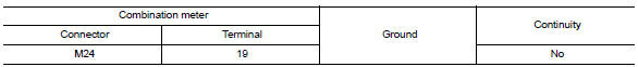
Is the inspection result normal? Yes >> go to 2.
No >> repair or replace harness or connector.
2.Check ambient sensor signal ground circuit
Check continuity between combination meter harness connector and ambient sensor harness connector.
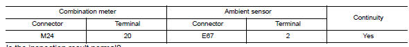
Is the inspection result normal? YES >> Inspection End.
NO >> Repair or replace harness or connector.
Component Inspection
1.Check ambient sensor
- Turn ignition switch OFF.
- Disconnect ambient sensor connector.
- Check resistance between ambient sensor terminals.
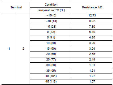
Is the inspection result normal? Yes >> inspection end.
No >> replace ambient sensor. Refer to hac-106, "removal and installation".
 Parking brake switch signal circuit
Component function check
1.Check parking brake switch operation
Check that brake warning lamp in combination meter turns on/off when parking
brake is actuated.
Is the inspection result normal?
...
 A/c auto amp. Connection recognition signal circuit
Description
A/c auto amp. Transmits the a/c auto amp. Connection recognition signal to
the combination meter
Diagnosis procedure (with manual a/c)
Regarding wiring diagram information, refer to ...
Other materials:
Wiper blade
Wiper blade
WIPER BLADE : Removal and Installation
REMOVAL
Put the wiper arms in the service position.
Turn the ignition switch ON and then OFF.
Within 1 minute, activate washer switch 2 times in less than 0.5 seconds
to put the wiper arms in the service
position.
Lift the w ...
Hvac branch line circuit
Diagnosis procedure
1.Check connector
Turn the ignition switch OFF.
Disconnect the battery cable from the negative terminal
Check the terminals and connectors of the a/c auto amp. For damage, bend
and loose connection (unit
side and connector side).
Is the inspection result normal?
...
iPod®* player operation with Navigation System (if so equipped)
Connecting iPod®
WARNINGDo not connect, disconnect or operate the
USB device while driving. Doing so can be
a distraction. If distracted you could lose
control of your vehicle and cause an accident
or serious injury.
CAUTION
Do not force the USB device into the
U ...
