Nissan Sentra Service Manual: Washer fluid level switch circuit
Description
Transmits the washer level switch signal to the combination meter.
Diagnosis procedure
Regarding Wiring Diagram information, refer to MWI-28, "Wiring Diagram".
1.Check washer level switch signal circuit
- Turn ignition switch off.
- Disconnect combination meter connector and washer fluid level switch connector.
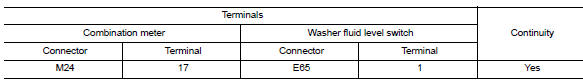
- Check continuity between combination meter harness connector and washer fluid level switch harness connector.
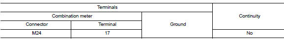
- Check continuity between combination meter harness connector and ground.
Is the inspection result normal? YES >> GO TO 2.
NO >> Repair or replace harness or connector.
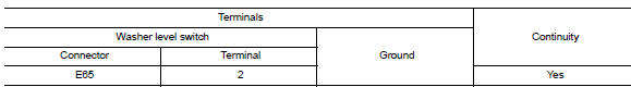
2.Check washer fluid level switch ground circuit
Check continuity between washer fluid level switch connector and ground.
Is the inspection result normal? YES >> Inspection End.
NO >> Repair or replace harness or connector.
Component inspection
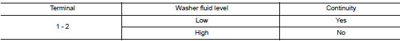
1.Check washer fluid level switch
Check continuity between washer fluid level switch terminals 1 and 2.
Is the inspection result normal?
Yes >> inspection end.
No >> replace washer fluid level switch.Refer to ww-53, "removal and installation".
 A/c auto amp. Connection recognition signal circuit
Description
A/c auto amp. Transmits the a/c auto amp. Connection recognition signal to
the combination meter
Diagnosis procedure (with manual a/c)
Regarding wiring diagram information, refer to ...

Other materials:
Ecu diagnosis information
BCM
Reference value
Note:
The signal tech ii tool (j-50190) can be used to perform the following
functions. Refer to the signal tech ii
user guide for additional information.
Activate and display tpms transmitter ids
Display tire pressure reported by the tpms transmitter
Read TPMS DTCs ...
Unexpected pedal reaction
Diagnosis Procedure
1.CHECK BRAKE PEDAL STROKE
Check brake pedal stroke. Refer to BR-15, "Adjustment".
Is the stroke too big?
YES >>
Bleed air from brake line and hose. Refer to BR-17,
"Bleeding Brake System".
Check brake pedal, brake booster, and maste ...
Cylinder head
Exploded View
Cylinder head assembly
Cylinder head bolt
Cylinder head gasket
Refer to INSTALLATION
Removal and Installation
REMOVAL
Release fuel pressure. Refer to EC-143, "Work Procedure".
Drain engine coolant and engine oil. Refer to CO-12, "Changing En ...
