Nissan Sentra Service Manual: Steering switch (meter control switch) signal circuit
Diagnosis Procedure
Regarding wiring diagram information, refer to mwi-28, "wiring diagram".
1.Check combination meter input signal
- Turn ignition switch on.
- Measure voltage between the following terminals of the combination meter.
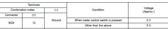
Is the inspection result normal? Yes >> inspection end.
No >> go to 2.
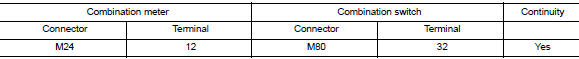
2.Check steering switch signal circuit
- Turn ignition switch OFF.
- Disconnect combination meter connector m24 and combination switch connector m80.
- Check continuity between combination meter harness connector and steering switch harness connector.
- Check continuity between combination meter harness connector and ground.
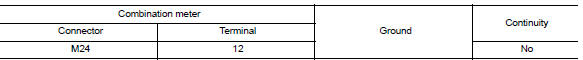
Is the inspection result normal? Yes >> inspection end.
No >> repair or replace harness or connector.
Component Inspection
1.Check steering switch
Check continuity between spiral cable terminals.
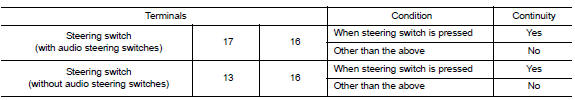
Is the inspection result normal? Yes >> inspection end.
No >> replace steering switch. Refer to st-10, "removal and installation".
 Power supply and ground circuit
Combination meter
COMBINATION METER : Diagnosis Procedure
Regarding Wiring Diagram information, refer to MWI-28, "Wiring Diagram".
1.Check fuses
Check that the following fuses are not bl ...
 Illumination control switch signal circuit
Diagnosis procedure
Regarding wiring diagram information, refer to mwi-28, "wiring diagram".
1.Check combination meter input signal
Turn ignition switch on.
Check voltage between the ...
Other materials:
Connecting procedure
NOTE:
The connecting procedure must be performed
when the vehicle is stationary. If the
vehicle starts moving during the procedure,
the procedure will be cancelled.
To connect a phone to the Bluetooth® Hands-
Free Phone System:
Press the SETTING button.
Use the TUNE/FOLDER knob to s ...
Intermittent Incident
DESCRIPTION
Sometimes the symptom is not present when the vehicle is brought in for
service. If possible, re-create the
conditions present at the time of the incident. Doing so may help avoid a No
Trouble Found Diagnosis. The fol-
lowing section illustrates ways to simulate the conditions/env ...
Fuel injector and fuel tube
Exploded View
Bracket
Fuel tube bracket
Fuel feed tube
Quick connector cap
Fuel tube
O-ring (black)
Fuel injector
O-ring (green)
Injector clip
CAUTION:
Do not remove or disassemble parts unless instructed.
Removal and Installation
WARNING:
Put a “CAUTION: FLAM ...
