Nissan Sentra Service Manual: S terminal circuit
Description
The output voltage of the generator is controlled by the IC regulator at terminal “S” detecting the input voltage from battery.
The “S” terminal circuit detects the battery voltage to adjust the generator output voltage with the IC voltage regulator.
Diagnosis procedure
Regarding wiring diagram information. Refer to chg-9, "wiring diagram".
1.Check “s” terminal connection
- Turn ignition switch OFF.
- Check if “s” terminal is clean and tight.
Is the inspection result normal? Yes >> go to 2.
No >> repair “s” terminal connection. Confirm repair by performing complete charging system test using exp-800 ni or gr8-1200 ni (if available). Refer to the applicable instruction manual for proper testing procedures.
2.Check “s” terminal circuit
Check voltage between generator harness connector and ground.
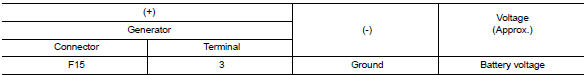
Is the inspection result normal? Yes >> refer to chg-14, "work flow (with exp-800 ni or gr8-1200 ni)" or chg-17, "work flow (without exp-800 ni or gr8-1200 ni)".
No >> check harness for open between generator and fuse.
 L terminal circuit (short)
Description
The terminal “l” circuit controls the charge warning lamp. The charge warning
lamp turns on when the ignition
switch is set to on or start. When the generator is providing s ...
 Symptom diagnosis
Charging system
Symptom table
...
Other materials:
Symptom diagnosis
The eco mode indicator lamp does not turn on
Description
The ECO mode indicator lamp does not turn ON when the ECO mode switch is
operated.
Diagnosis Procedure
1.Perform combination meter on board diagnosis
Perform combination meter on board diagnosis. Refer to MWI-16, "Description" ...
Clutch disc and clutch cover
Exploded View
Flywheel
Clutch disc
Clutch cover
Input shaft
First step
Final step
Apply lithium-based grease
including molybdenum disulphide.
Removal and Installation
CAUTION:
Do not reuse CSC (Concentric Slave Cylinder). The CSC slides back
to the original posit ...
Primary speed sensor
Exploded View
Transaxle assembly
O-ring
Primary speed sensor
: Always replace after every
disassembly.
: N m (kg-m, in-lb)
: Genuine NISSAN CVT Fluid NS-3
Removal and Installation
REMOVAL
Disconnect the primary speed sensor connector.
Remove the primary speed sensor.
...
